
FACE Reveal
In the last article we dug into the YM3812 registers and how to manipulate them an electrical level. Today we are going to build up the first part of the schematic—just enough to get sound working through a microcontroller.
Whenever building on a new platform, What’s the first thing you implement? Hello World. It’s a great starting point that ensures everything works—the hardware, the development toolchain, etc. We need an equivalent project for our YM3812 that uses sound instead of text on the screen. We need… a FACE reveal! (you know… play an F major 7th chord… F A C E… yeah… woof… #DadJokes 🙄). OK but seriously… to play a note on this chip, we need working hardware, a library that interfaces with the chip, a properly configured voice, and the ability to turn on/off a note at the right frequency. This is going to be an epic journey… and it’s going to take two articles to complete. In this article, we will start with the hardware and schematic, and then upload the code from the GitHub repo using the Arduino IDE. Then in the next article, we will look into the code in a bit more detail to see exactly how it’s working.
The Components
In the spirit of starting small, I’ve pulled together a simple implementation of the YM3812 hardware. Technically, you could simplify this further—interfacing the full 8-bit data bus directly with the microcontroller, or having the microcontroller produce the 3.58 MHz clock. But we are going to need some of those pins down the line and this all fits on a single breadboard. Let’s take a look at our cast of silicon characters.
AVR128DA28 Microcontroller
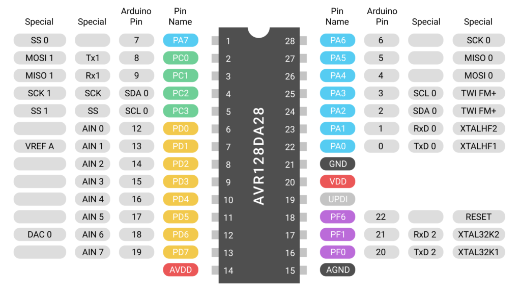
I like to think of the AVR128DA28 as an Arduino Nano, but in chip form—and far more capable. This chip sports:
- 128kb of program memory and16kb of ram
- 10 AD converters, and a DA converter
- I2C, SPI, UART, and even 4 hardware serial ports
- Operating voltage of 1.8v to 5.5v
- Internal auto-tuned 24 MHz oscillator
- UPDI programing & Arduino IDE Support
- And sooooo much more…
All in an itty bitty 28pin DIP package. There are even more powerful surface mount versions of the chip as well, but this will give us plenty of oomph in our project. I have to give a shout out here to Robbie Langmore from Tangible Waves for introducing me to these microcontrollers. In a world of chip shortages, there are still ~300 in stock at mouser—as of writing this.
74HC595 Shift Register
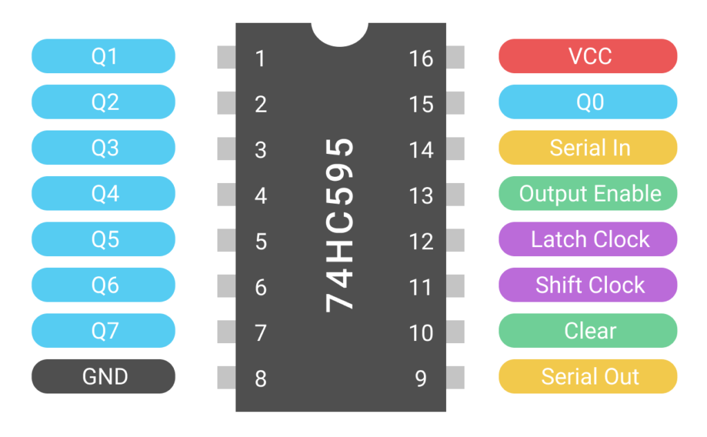
The 74HC595 shift register is next in our lineup. This chip converts the serial output from the AVR’s SPI bus and converts it into the 8-bit parallel bus that bus required by the YM3812.
YM3812 OPL2 Sound Processor
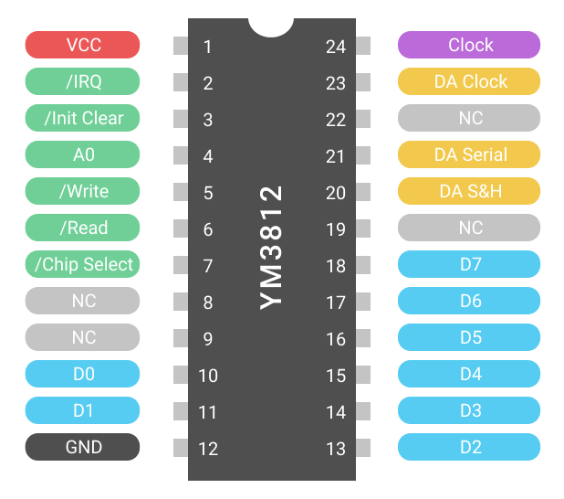
If you are reading this article and wondering what this chip does, then I highly recommend reading part one of this series. Other than some decoupling capacitors, the YM3812 requires a a 3.58Mhz crystal oscillator.
Y3014B DAC
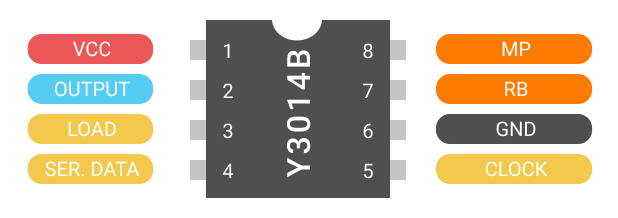
Unlike some of the other YM sound processors, the YM3812 does not have an analog output. Instead, it needs to be paired with the Y3014B 10-bit Digital to Analog Converter. This chip takes a serial data stream coming from the YM3812 and converts it into an analog output. The Y3014B requires a voltage of 1/2 VCC on pin 8 (MP) to bias the output signal (pin 2) around. Fear not though, it produces its own reference voltage on pin 8 (RB), but you still need to buffer that voltage using an operational amplifier. Also, buffering the output signal (pin 2) with an operational amplifier is another solid plan.
TL072 / LM358 OpAmp
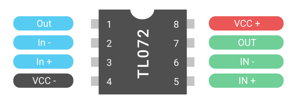
Did somebody say operational amplifier? OpAmps are the workhorses of Eurorack Modules and Analog Circuitry in general. Unless it’s a passive attenuator, odds are, there’s going to be 1 or maybe 10 of these versatile building blocks. In our case, will use these to buffer the reference voltage and output signal generated by the Y3014B.
Other Parts
After the ICs, there’s only a handful of other parts.
- The six .1uF capacitors provide decoupling for the ICs
- The two 10 uF capacitors stabilize the reference voltage on the Y3014b
- And the 4.7 uF capacitor provides capacitive coupling on the audio output
- The 100k resistor ties the output capacitor to ground and the 1k resistor ensures appropriate output impedance
- The 1N4148 signal diode converts the single-wire UDPI pin into separate Tx/Rx pins that attach to an FTDI cable
- Lastly, a micro-switch provides a reset button for the AVR microcontroller.
Schematic Time!
Microcontroller Connections
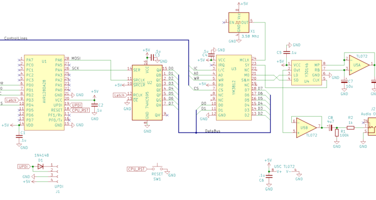
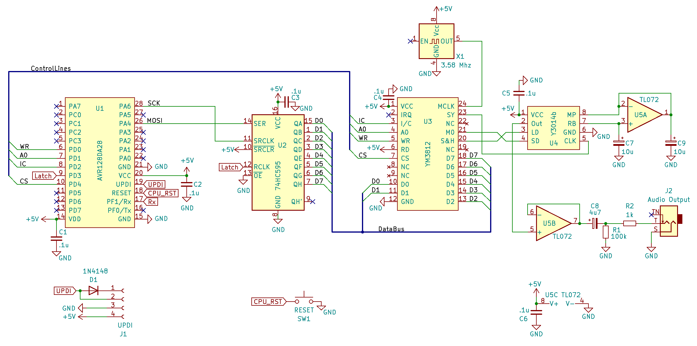
Now that we’ve talked through how the pieces work, the schematic should seem pretty straightforward. The Clock (pin 26) and Data (pin 28) of the SPI bus of the AVR128DA28 connects to the Serial Data (pin 14) and Shift Clock (pin 11) inputs on the 74HC595 shift register. PortD-3 (Pin 9) on the microcontroller connects to the Latch Clock (pin 12) on th 74HC595 and latches the output of the register. This sends the 8 Data Bits (pins 15, 1-7) to the YM3812 Data Inputs (pins 10-11, 13-18).
PortD 0, 1, 2 and 4 (pins 6, 7, 8, 10) on the microcontroller connect to the four control lines of the YM3812—Write (pin5), A0 (pin 4), Initialize/Clear (pin 3), and Chip Select (pin 7) respectively. On the YM3812, tie Read (pin 6) high to prevent rogue reads. IRQ (pin 2) can be left floating in the breeze.
Sound Processor & DAC Connections
The Output of the 4.58 MHz Crystal Oscillator flows in to the Master Clock Input (pin 24) on the YM3812. Enable (pin 1) on the oscillator should float. Tying it to ground disables the clock output.
The Serial Data and Clock output pins on the YM3812 connect to the Serial Data and Clock input pins on the Y3014B and transfers the raw sound data to the DAC. Sample & Hold (pin 20) on the YM3812 connects to the Latch (pin 3) on the Y3014B, and updates the analog value of the output.
The Y3014B produces a reference voltage of 1/2 VCC on RB (pin 7) which the TL072 then buffers and sends back to the output bias control pin MP (pin 8) on the Y3014B. C7 and C8 stabilize the reference voltage.
The Analog Output signal of the Y3014B (pin 2) get buffered through another operational amplifier on the TL072 before passing through a coupling capacitor (C8) to remove the DC bias. A high value resistor (R1) ensures our output stays centered at ground, and R2 ensures our output remains at a 1k impedance.
The Other Stuff
Of course all of the ICs require decoupling capacitors on their power pins (C1 – C6). And a reset button connects the Reset Line (pin 18) of the AVR128DA28 to ground. As far as I can tell, the reset button doesn’t require a debouncing filter, you can just directly connect it.
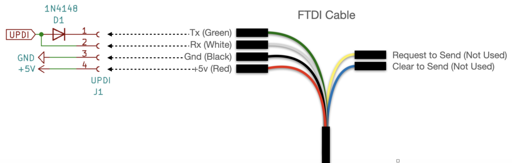
Lastly, the AVR128DA28 can be programmed through a one-wire Universal Programming & Debugging Interface. If you don’t have one of those programmers, you can use an FTDI to USB connector. There are many variations of this connector, some include the RTS/CTS lines (which we don’t use) and some don’t. Also, there are a couple of color variations of the wires on the connector. Here is an alternate color scheme that I have seen:
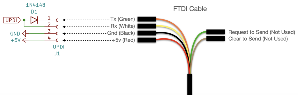
FTDI Cable with Alternate Color Combination
Starter Code
Our circuit isn’t going to do much without a bit of code. We need to program the microcontroller to see if everything works. As it happens that I created a simple library on my GitHub for just that purpose. I’ve trimmed it down to its basic elements and added loads of comments to make things as readable as possible. Feel free to download and play around with it, and in the next video we’ll dive into exactly how the code works.
Note, to get the YM3812_Breadboard.ino file to work, you will need to create a “YM3812_Breadboard” folder in your Arduino folder and then copy YM3812_Breadboard.ino, YM3812.h, and YM3812.cpp into it.
Programming the Micro
Assuming that you chose to use an AVR128DA28 as your microcontroller, you’ll need to install the DxCore in your Boards Manager. DxCore is an open sourced library written by Spence Konde that allows you to use the AVR128 line of microcontrollers in the Arduino IDE. There are detailed installation instructions on the GitHub, but this should at least get you started.
First we need to add a URL to the Additional Boards Manager URLs. To do that, open the menu: Arduino > Preferences:
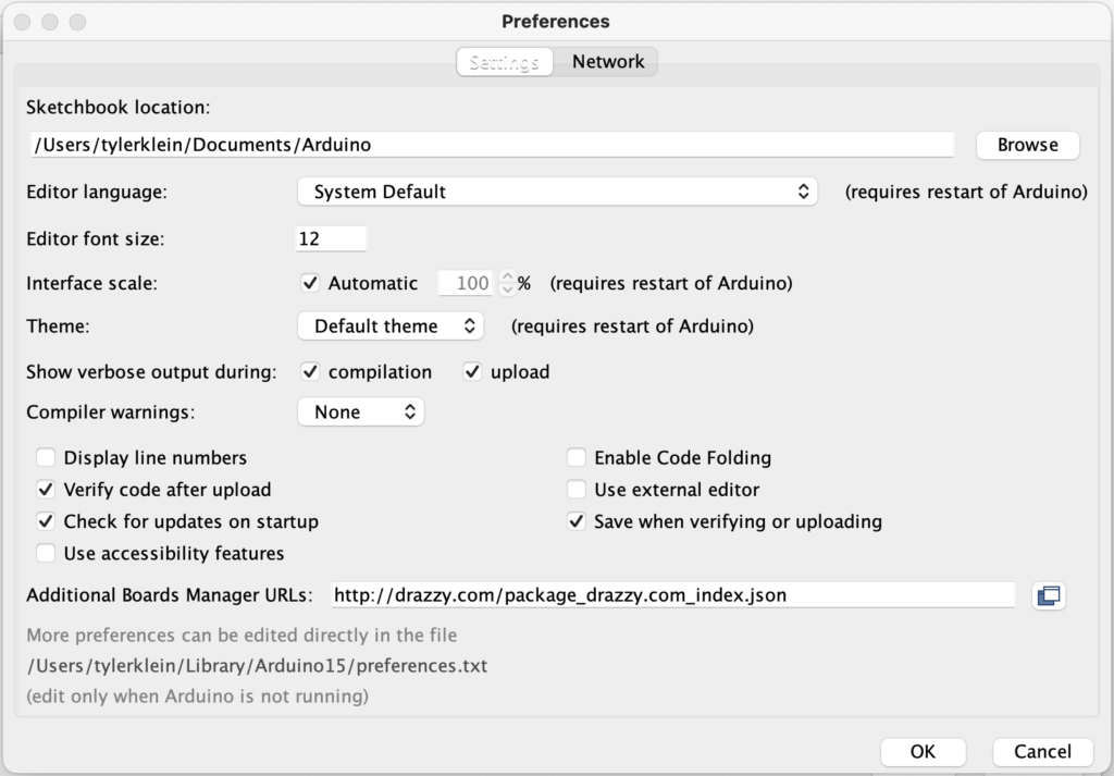
Enter the url, http://drazzy.com/package_drazzy.com_index.json in the Additional Boards Manager URLs text box as shown above.
Then, locate the boards manager in Tools > Boards:… > Boards Manager
Search for DxCore and locate a package that looks similar to the one below:
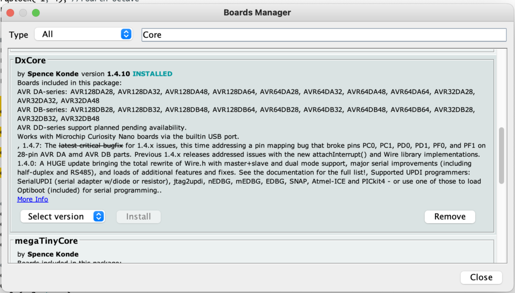
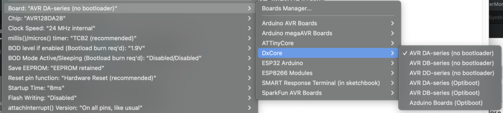
After installing the DxCore boards library, you should be able to select the AVR DA-series (no bootloader) from the board menu. Also, select AVR128DA28 as the chip, and 24 MHz Internal as the Clock Speed.
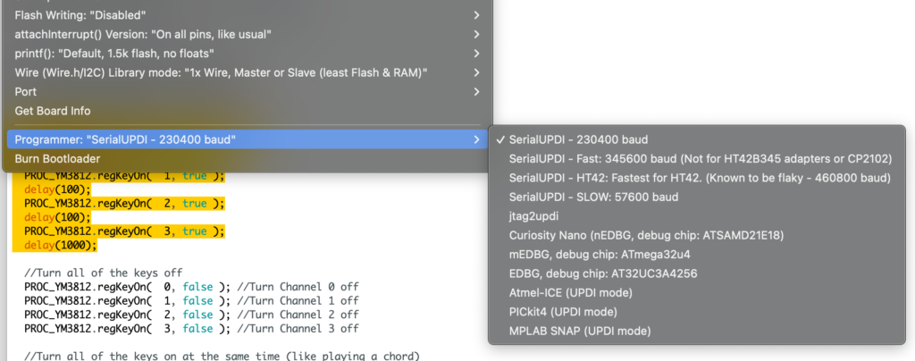
The programmer that worked best for me was SerialUPDI – 230400 baud. It’s quite fast.
Now, just connect your FTDI cable as described in the schematic section of this article. And fingers crossed your program should upload directly into the micro. If it doesn’t… check that the Tx/Rx pins aren’t swapped—I’ve done that a few times.
Final Thoughts
With any luck, you have now experienced the total exhilaration of getting the YM3812 to generate that F Major 7 chord! Realistically, ANY sound at this point is great, because it shows that the hardware is working. If you got everything working, feel free to leave a comment. Similarly, if you see any issues in the schematic, let me know. After all, I’m still learning too!
In the next article, we will look through the code in detail.
Errata
- In the schematic, the labels on the SPI Clock and MOSI lines were swapped. Thank you to Peter Hesterman for catching this one!