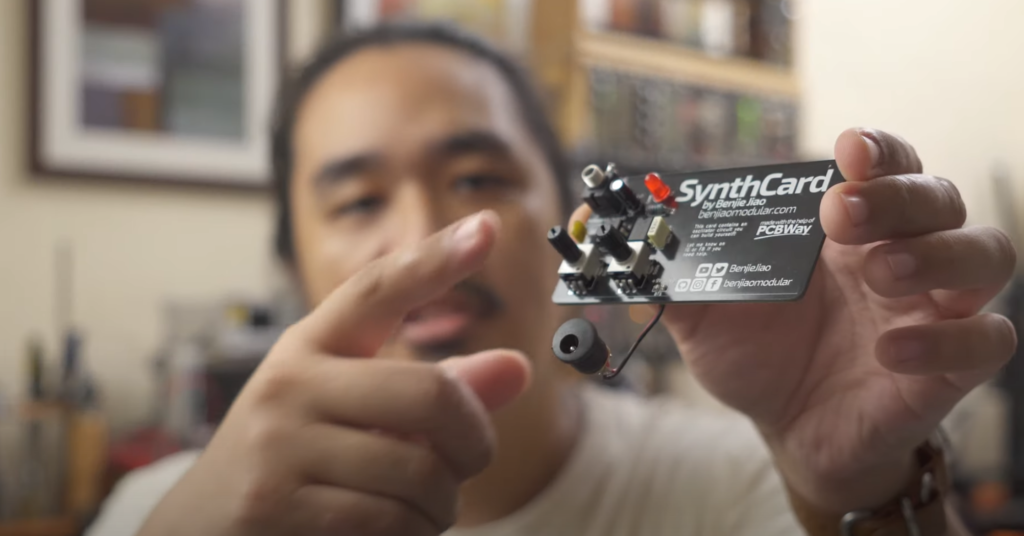
At the end of 2022, Benjie from Benjiao Modular released an Atari Punk Console synthesizer using a couple of 555 timer chips and a handful of other components. Now, there are lots of 555-based synthesizers out there, but in this case he printed it onto a PCB the size of a business card and added his contact information into the silkscreen of the PCB. Thus the SynthCard was born!
This clearly genius idea gained traction and soon others followed. Karltron created a triple VCO/LFO SynthCard, and Juanito Moore of Modular for the Masses created an 808 Kick Drum and MS-20 style filter.
Now, I don’t want to get too side tracked here because ultimately, we are still trying to build a YM3812 EuroRack module. But, all of the hardware we’ve needed for the first eight articles of this series fit nicely onto a single breadboard. And that got me wondering… would it be possible to fit all that onto a SynthCard sized PCB? What if it could only use through-hole components?
Well, this wouldn’t be much of an article if you couldn’t, so… yes! You totally can!
The YM3812 SynthCard
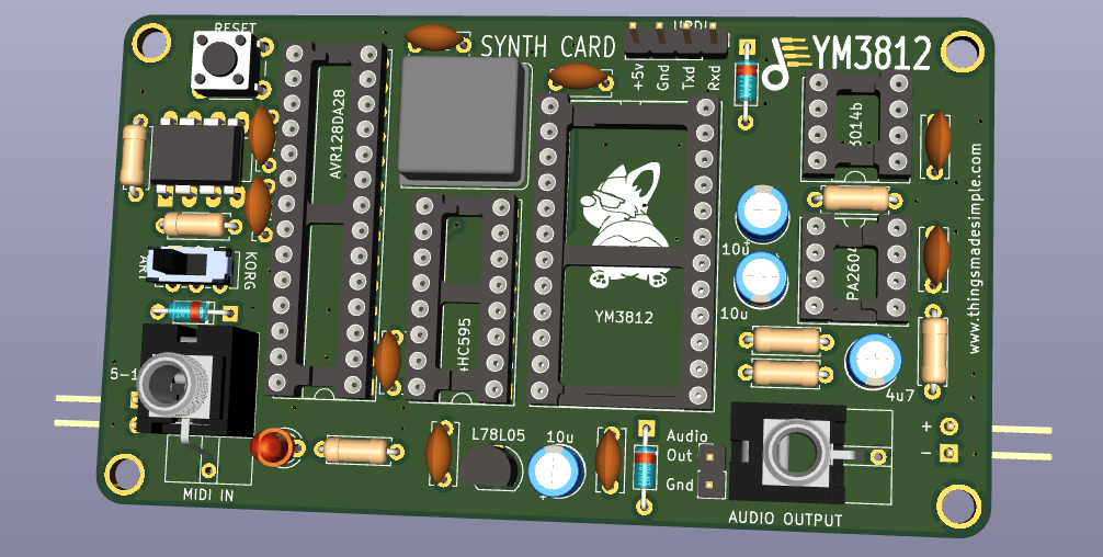
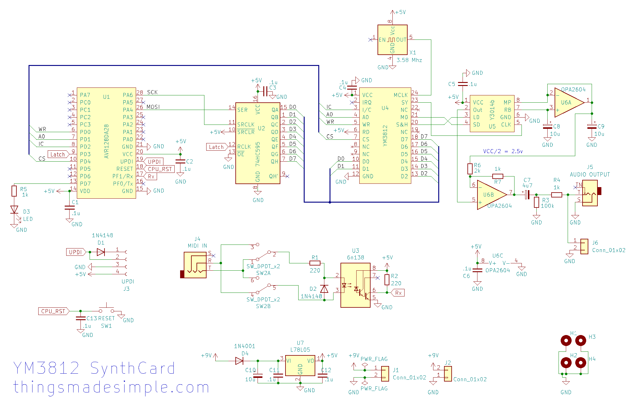
This business card sized module takes a MIDI input, generates sound using a YM3812 OPL2 sound processor and then outputs that sound through a mono jack. The schematic for this is basically the same as the one we created all the way back in article 4, but I’ve included a status LED and also a 5v voltage regulator.
It also has all of the same great features implemented so far:
- Support for the General MIDI 1.0 patches and instrument selection
- Support for percussion patches on MIDI channel 10
- Support for level control for on each incoming note
What can I do with it?
My favorite use case for this module is to send it General MIDI music from video games. While you might think it would sound the same as an Adlib card—because it has the same OPL2 sound chip—the instrumentation can be quite different. For example, take a look at this side by side comparison of Leisure Suit Larry 3:
Notice how the original Adlib instrumentation uses far fewer voices than the General MIDI? I find that very strange because both the Adlib card and this SynthCard use the same OPL2 chip. While the OPL2 chip is clearly capable of playing more sophisticated music, the Adlib instrumentation doesn’t take advantage of it. This leads me to believe that perhaps the original Adlib composition statically assigned patches to each voice and kept them the same throughout the song. Perhaps dynamically reassigning them was too CPU intensive? If anyone knows the answer here, I’d love to hear it!
Bottom line, General MIDI music rendered on an OPL2 chip sounds very different in this game. (I dare say, even better!)
How do I get one?
This turns out to be incredibly cheap and easy. Go to my GitHub and download the YM3812_SynthCard.zip file.

Then go to JLCPCB (or p C B WAAAAaaay!) whichever PCB manufacturer you like best, and drag the zip file onto the “Add Gerber File” box. After a few seconds, you will see an order form. There are only a couple of key changes to make:
The most important change is to select LeadFree HASL. Sure it adds $1 to the price, but since this is supposed to be like a business card that you can pass around and handle… with your hands… you really want to avoid getting lead poisoning. And with my name on it… I just don’t want to feel responsible for that. So please, go unleaded. (And print at your own risk).
OK, enough disclaimers. From here you are able to select your favorite color and then you can also choose “Specify Location” for the Remove Order Number option. (I specified a location in the Gerber File).
From there, just go ahead and place your order! For the low, low price of $3 (plus ~$16 shipping and handling) you get not one… but TWO boards. And if you act now, they will MORE THAN DOUBLE YOUR ORDER and send you FIVE BOARDS! Juuuuust kidding. This deal lasts forever (it’s their minimum order quantity). It’s still a pretty great deal though. So get 5 and pass the extras around to your friends!
How do I build one?
First, you are going to need a few parts. If you have been following along, you probably have most of these parts already—especially the AVR microcontroller, the YM3812, Y3014b, and other chips, as well as the passive components. This board adds just a few new components that you’ll need to source. Specifically, a 78L05 voltage regulator (in a TO-92 package), a 1N4001 rectifier diode, and a mono (black) thonkiconn jack and a stereo (green) thonkiconn jack. For U6 I’m using an OPA2604 operational amplifier instead of a TL072 because this is a single power rail design, but in theory, you might be able to get away with an alternative op-amp. Just play with it a bit.
Bill of Materials
Here is the full list of materials that you will need to populate the board:
| CAPACITORS: | ||
| • 100 nF (Ceramic) | x9 | C1-C6, C11-C13 |
| • 4.7 uF (Electrolytic) | x1 | C7 |
| • 10 uF (Electrolytic) | x3 | C8-C10 |
| RESISTORS: | ||
| • 220R (Axial) | x2 | R1, R2 |
| • 100K (Axial) | x1 | R3 |
| • 2K (Axial) | x1 | R6 |
| • 1K (Axial) | x3 | R4, R5, R7 |
| DIODES: | ||
| • 1N4148 Signal Diode(Axial) | x2 | D1, D2 |
| • 1N4001 Rectifier Diode (Axial) | x1 | D4 |
| • LED (3.0mm) | x1 | D3 |
| JUMPERS: | ||
| • Pin Header 01×02 2.54mm Vertical | x3 | J1, J2, J6 |
| • Pin Header 01×04 2.54mm Vertical | x1 | J3 |
| JACKS: | ||
| • MIDI IN: Green Thonkiconn Stereo 3.5mm Audio Jacks (PJ366ST) | x1 | J4 |
| • AUDIO OUTPUT: Thonkiconn Mono 3.5mm Audio Jacks (PJ398SM) | x1 | J5 |
| SWITCHES: | ||
| • RESET: 6mm Push Button Switch | x1 | SW1 |
| • MIDI Input Type: DPDT E-Switch EG2271 | x1 | SW2 |
| ICS & SOCKETS: | ||
| • AVR128DA28, DIP 28 7.62mm | x1 | U1 |
| • 74HC595, DIP 16 7.62mm | x1 | U2 |
| • 6n138, DIP 8 7.62mm | x1 | U3 |
| • YM3812, DIP 24 15.24mm | x1 | U4 |
| • Y3014b, DIP 8 7.62mm | x1 | U5 |
| • OPA2604, DIP 8 7.62mm | x1 | U6 |
| • L78L05, TO-92 | x1 | U7 |
| • 3.58 Mhz Crystal Oscillator, DIP-8 (Square) | x1 | X1 |
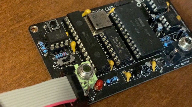
Putting it together
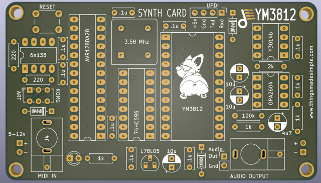
Hopefully the labeling is mostly self explanatory. On the front, I’ve listed all of the component values, and on the back, you’ll find all of the component reference numbers. Here are the usual tips and gotchas for building modules:
- Start with the smallest / flattest components first—This is a pretty densely populated board, so soldering things on in the right order will make your life easier. Start with the resistors, diodes, capacitors, and voltage regulator. Then move on to the switches, ICs and the oscillator. Finally solder on the jumpers and Thonkiconn jacks.
- Check the alignment of polarized components. The line on the diode should match the line on the board. The strip on the electrolytic capacitors should match the white silk screen on the board. The 78L05 should align to the shape in the silk screen. The longer pin of the LED should go in the round hole. The notch in the ICs (or IC sockets) should match the notch on the board. The square corner of the oscillator should match the corner on the silk screen.
- Sockets vs. No Sockets – This is totally up to you. I personally use sockets, but I know there are lots of arguments on why NOT to use sockets (the connections fall out, sometimes they cost as much as the chips, etc.). I would recommend using a socket for the YM3812, Y3014b and the AVR128DA28 as those are either the rarest and/or most expensive chips on the board. To be on the safe side, you might want to power up the board and test the voltages before plugging them in.
- Stereo (Green) Thonkiconn jack is used for MIDI In, and the Mono (Black) Thonkiconn jack is used for the Audio Output.
Powering Up!
The 5v regulator allows you to power this device using anything from 6v to 12v DC. No negative voltages are required, so you could use a 9v battery, an external power supply, or even just plug it into the positive end of a EuroRack connector.
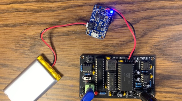
Alternatively, you can plug a regulated 5v supply into the UPDI header at the top of the card. This allows you to power the device directly from an USB to FTDI cable or even an external Li-Po battery.
CAUTION: The regulated power connectors on the left and right side of the board have reverse polarity protection, but the 5v connector on the top does not. Be sure to only use 5v and make sure you plug it in the right way around!
Uploading the firmware
The firmware for this module is exactly the same as what we’ve built throughout the article series thus far. Just go find the latest code from Article 8 and then upload it from the Arduino IDE using an FTDI cable. There are lots of details on how to do that throughout this series, but especially in Article 2.
Usage and Troubleshooting
To use a MIDI cable, you will need an adapter. These are pretty easy to find online, but there are several different versions. You will want a version that connects pins 4 and 5 of the MIDI connector to the tip and ring of the 3.5mm jack. I talk more about the different standards in Article 4 if you want some more background. Depending on which version of the adapter you get, you may need to change the direction of the Korg/Art switch on the left side of the SynthCard. If you have a beat step pro or another device that uses a TRS jack for MIDI output, you may be able to connect it directly using a 3.5mm stereo audio cable (no adapter required!).
If you turn the device on and the red activity light just stays on, press the reset button a bunch of times until it turns off. I have yet to track down why that happens. If you guys have any ideas, let me know in the comments!
If things still don’t work, check that all of the polarized parts are in the right way around.
You want some more?
Well, you are in luck! Benjie put together a website, synthcard.com, to host other SynthCard projects! I hope others will join in the fun and create even more mini-synth business card goodness. If you want jump into the conversation, then head on over to the Modular for the Masses discord community.
Errata
- The microswitch was labeled as an EG1271 which is an SPDT switch. The correct part should be EG2271 which is a DPDT switch. Many thanks to Peter for debugging this one and identifying the issue!
 By
By 
9 thoughts on “YM3812 Part 9 – Synth Card”
Peter Hesterman
Tyler,
I’ve built two of these now and could use some troubleshooting advice as I’m having the same problem with both of them. I know they both work because the Breadboard.ino sketch works fine on each of them. The problem is with MIDI (and I know it’s on the hardware side—Velocity.ino works, too, if I call handleNoteOn and handleNoteOff directly). Neither responds to any MIDI input…I’ve used a store-bought Korg-type DIN->TRS adapter, made and tried my own Korg-type and Beatstep-type adapters, tried different switch positions with both, etc., etc. I’ve checked and re-checked the solder joints and diode polarity, replaced the 6N138 ics, and so on. Nothing happens…the activity light doesn’t flicker. Can you suggest anything? Should I remove the Thonikonn stereo jack and try wiring in a DIN jack instead? Replace the switch?
Thanks,
Peter
Tyler in reply to Peter Hesterman
First off, I admire your persistence! If you built it twice and neither are working, there must be something subtle at play. Here are a couple of thoughts…
I would double check that the tip and ring of the connector actually connect to the correct pins on the DIN side of the connector. There are a number of different standards. Two of them reverse the connections (hence the switch). But there are also a few versions that connect to completely different pins on the DIN connector.
If continuity checks out there, then the next step would be to follow the signal from the MIDI input, into the 6n138 and then into the microcontroller. If that all works…
Then it could be a software issue. Are you using the AVR128DA28? or a different microcontroller? The AVR has a number of different serial ports. It’s possible that the software is looking to the wrong port?
Hope that helps!
-Tyler
Peter Hesterman
Tyler,
Thanks for the reply. Using my continuity tester, I discovered that there’s clearly something wrong between the MIDI IN jack and the 6N138…the tip and ring seem to be connected somehow! I’m wondering if I’m using the wrong switch. Your parts description above refers to the switch as a “DPDT E-Switch EG1271,” but when I looked at Digi-Key, it says the EG1271 is a SPDT switch. I know that what I’m using was sold to me as an EG1271…is it possible that it should be the DPDT type instead?
I pulled the 6N138 and input MIDI directly to where 6N138’s pin 6 would have been…everything worked, so no software or microprocessor problem (and, I am using the AVR128DA28).
Peter
Tyler
Hey Peter,
That’s some solid debugging, and I think you have 100% discovered the issue. SPDT stands for “Single Pole Double Throw.” That means that there is one connector (single pole) that can be connected to one of two points (double throw). DPDT stands for “Double Pole Double Throw.” That means that there are two different connectors (double pole) that can each go to two different points (double throw). It’s sort of like two completely separate switches that are physically connected so they switch at the exact same time.
By using a single pole double throw, you are basically connecting all of the wires of each of the two switches together.
You can probably either get a DPDT switch or skip the switch and just manually connect the inputs to the circuit. You may just have to swap which wire goes to which point on the circuit (tip or ring) depending on the MIDI to TRS connector. But hey, at least you can test it and get it to work!
In terms of skipping the 6n138, I wouldn’t recommend plugging MIDI directly into the microcontroller. The 6n138 is there to fully isolate the microcontroller from the outside world so nothing bad happens to it… Anyway just swap out the switch and I bet everything will work perfectly!
Tyler
So I went back and verified the part number. It should be EG2271 not EG1271. They look identical, but the EG2271 is DPDT instead of SPDT. Thank you for identifying the issue! That is 100% my bad—so sorry for the confusion there! I will update the parts list above to reflect the change.
Peter Hesterman
Thanks! That should be an easy fix then. And, thanks again for sharing this project…I’ve had a great time following along and working on it!
Peter
Olivier
I built one, but I’m unable to program it. Additionally, the LED doesn’t light up when connected to either the FTDI cable or a 9V battery. I’ve checked, and I’m getting 5V output from the L78L05.
Regarding the switch, I couldn’t find the original one in stock, so I purchased this alternative. I hope this isn’t causing the issue.
https://www.mouser.ca/ProductDetail/Nidec-Components/CL-SB-22C-01?qs=XeJtXLiO41RGG9TnwtBv7A%3D%3D
Let me know if you think to something else I should verify.
Very cool project by the way.
Thank you.
Olivier
Tyler in reply to Olivier
Hey there Olivier, sorry for the delay, I just saw your messaging as I scrolled through about 1,200 spam messages. Some quick thoughts: The LED is software controlled, so it won’t turn on until the AVR is programmed. Assuming the hardware is set up properly (diode is facing the right direction, you are using an AVR128DA28 and not the AVR128DB28, etc.), you may need to follow different steps depending on what version of Arduino you are using. If you are using the version where the logo is a circle, it should work just like it does in the article. If you are using a newer version of the IDE (the logo is a box with rounded corners) then you may need to program it from the menu: “Sketch” > “Upload Using Programmer” instead of clicking the normal arrow. As for the switch, I’m pretty sure that one won’t work… here is a link to the one that I used: https://www.aliexpress.us/item/2251832485877275.html?channel=twinner.
Good luck! Let me know if you get it to work!