If you followed along through last three posts, then hopefully you have a Yamaha YM3812 OPL Sound Chip on a breadboard playing a lovely F Major 7th chord over and over and over 😅. Or maybe, the annoying repetition drove you to experiment and find new patterns. It’s a great proof of concept that ensures the hardware and software work, but not exactly an instrument. Today, we are going to fix that by implementing MIDI. This way, you can use any external musical input device or even your computer to play music—not just sound. And that, to me, makes it an instrument.
The Hardware

Building hardware that interfaces MIDI with a microcontroller requires only a handful of components and is actually pretty simple. Fundamentally, the schematic just passes a serial TTL logic signal from the Tx pin of one microcontroller to the Rx pin of another. The real magic is that this circuit fully isolates the sender from the receiver. They don’t even need a common ground! Let’s see how.
Input & Output Combined

If you connect these two circuits through a MIDI cable, you get the schematic above. An LED inside the 6n138 optocoupler signals a light sensitive transistor. When the LED turns on, the transistor connects pins 5 and 6 of the optocoupler and allows electricity to pass through. When the LED turns off, that connection breaks. The 220 ohm pull-up resistor ensures that pin 6 stays high whenever the LED is off, and low when the LED turns on.
You can think of the other half of the circuit as an LED on an extension chord. 5v flows through two 220 ohm resistors before going through the LED inside of the 6n138. It then flows back through another 220 ohm resistors and into the Tx pin of the microcontroller. When the Tx pin goes high, both sides of the LED are at 5v and no current can pass. But when Tx goes low, the current sinks into the microcontroller and the LED turns on. Turning the LED on closes the connection of pins 5 and 6 on the 6n138 which shorts the Rx line to ground. This way when Tx goes low, Rx goes low—and visa versa.
Also take note that the ground connection that passes into the MIDI cable does not connect to the receiving circuit. This shields the cable from interference, but also keeps both sides fully isolated.
On another note, the placement of the resistors ensures that foul play by either device won’t hurt the microcontroller or the optocoupler. The extra diode ensures that even connecting these pins backwards won’t cause any damage to the 6n138.
MIDI TRS Jacks
If you are familiar with MIDI devices, then you may be wondering why I used a TRS (tip/ring/sleeve) jack instead of the traditional 5-pin DIN connector. And well, I can think of two good reasons: size and cost. Ultimately, I plan to create a set of patchable EuroRack midi devices that allow patching of MIDI signals just like CV or Audio. In this context, 5-pin DIN connectors (which can cost multiple dollars each) and their associated MIDI cables become prohibitively expensive—especially in comparison to TRS jacks and stereo patch cables. Not to mention that a patchwork of MIDI cables would become far too bulky for a EuroRack setup.
Of course, I am far from the first person to decide this, and DIN to TRS converters abound. So I purchased one used by big name brands like Korg and Akai. The circuits above are based on the pinout of these adapters. Later, I added a beat step pro to the mix.

The Beatstep Pro uses TRS jacks straight out of the box, so I happily connected my device with a stereo patch cable… and it didn’t work. This is because Arturio inverts the connection of the tip and ring. Of course you could just as easily say that Korg inverts the tip and the ring connections, because it all depends on your frame of reference. There is no fully standard way to convert between a DIN MIDI connector and a TRS jack. And now I had one Korg converter and two Arturio converters… what to do…
TRS Input Switchable Module
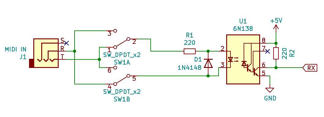
Well, this is easy… Just add a switch and then you can swap from one standard to the other! Besides, like I said earlier, that diode prevents anything bad from happening if you connect things backwards. After building this circuit dozens of times I finally just built a small module that plugs right into a breadboard. This makes things way more compact and simple:

You can find all of the the breakout board schematics and PCB files on GitHub in the Article 4 folder. I even included a zip file with a penalized layout that you can upload to your favorite PCB manufacturer and print out for dirt cheap. I think I got 20 copies for $2 USD through JLCPCB—though shipping probably cost 10x that.
Breadboard Schematic
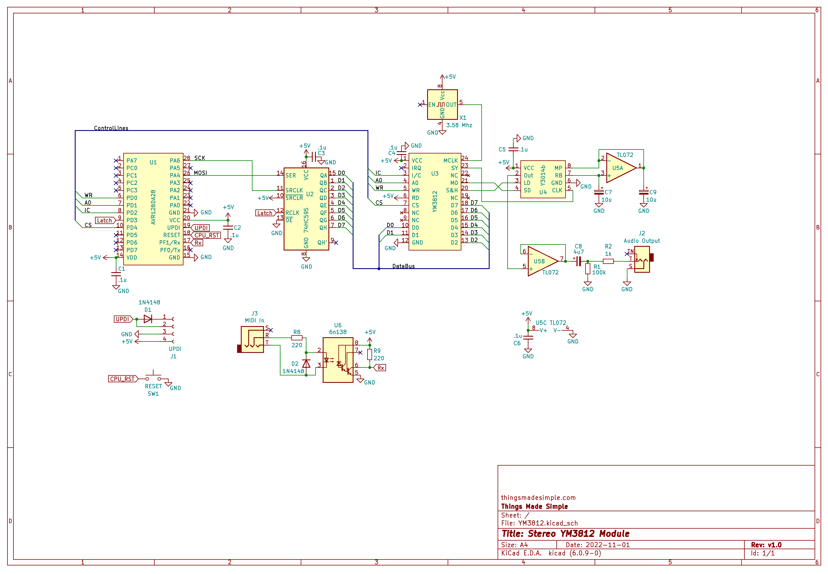
Anyway, how ever you build the circuit out, just hook up the Rx pin of the MIDI input to the Rx pin on the AVR128DA28. Now, we should be good to get to the software. Here is the full schematic for reference:
Frequency Nonsense
Before getting into the code that plays a MIDI note, we first need to understand how the YM3812 encodes frequencies. Looking at the register options, two settings control the pitch of a channel: FNum and Block. Note: F-Number splits across two 8-bit register bytes to form a 10-bit number. Block, on the other hand, uses only a 3-bit number.

According to the data sheet, the note frequency (fmus) connects to the F-Number and Block through the formula:

Note: “fsam” (or sample frequency) equals the master clock frequency (3.6 MHz) divided by 72.
Calculating F-Numbers
Now you may be asking yourself, why do we need more than one variable to select a frequency? And to figure that out, let’s try calculating the F-Num for every MIDI note’s frequency and every for block. To do this, I created a frequency number calculator. Feel free to open that up in another window and play along!
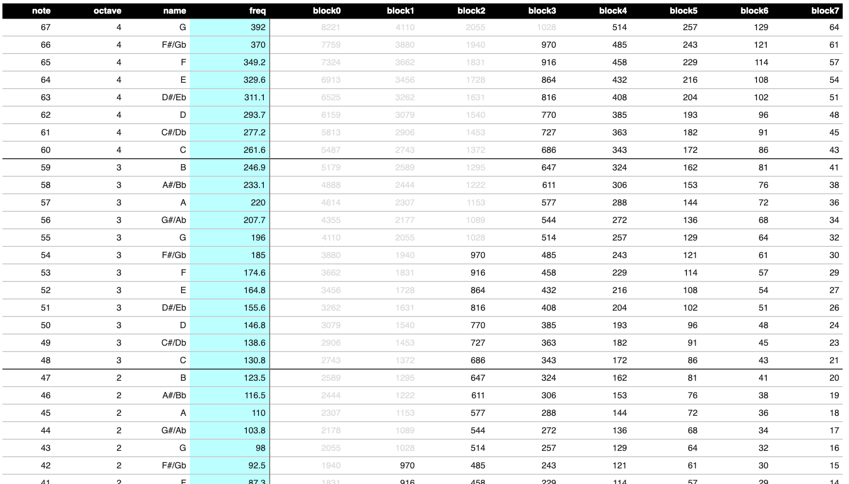
A couple of interesting insights become apparent when we do this.
- Depending on the block value used, some of the F-Numbers (shown in grey) end up being too large to represent using a 10-bit number. 10-bit numbers max out at 1023.
- Even with the maximum, you can still represent some frequencies with more than one block value / F-Num combination.
- Looking at the highest possible values in each column, they seem to follow a pattern: 970, 916, 864, etc. And comparing each instance of those numbers to the note name on the left, those numbers appear to be an octave apart. For example, 970 in block 3 represents F#4 where 970 in block 2 represents F#3. This seems to indicate that blocks are one octave apart.
Now the question remains: knowing we can represent a frequency with multiple block/f-num combinations, which block should we use? To figure that out, let’s use our newly calculated F-Numbers and block values in reverse to calculate the original note frequency.
Rounded Frequencies
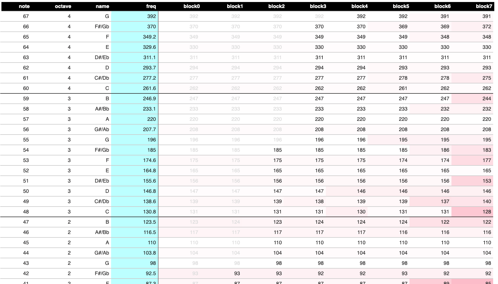
Now things are getting interesting. Some of the newly calculated frequencies are way off—especially for higher block numbers. Because F-numbers have no decimal component, they will always be somewhat inaccurate. Moreover, the lower the F-number, the more the inaccurate the frequency becomes. Take a look at the bottom of the table:

Yikes, that’s a lot of red! Even block 0 does a mediocre job of representing the midi note. Still, A0, which is the lowest note on the piano is MIDI note 21… so I suppose that’s not THAT bad… Everything below that is going to be difficult to hear anyway.
Let’s take this further and come up with a few general rules for choosing blocks and F-numbers. Namely:
- We always want to use the lowest possible block value and thus the highest—and most in-tune—F-numbers
- The note frequencies follow the same pattern across each block separated by 12 notes (one octave)
Building an Algorithm
With this in mind, I exported the top 31 F-Numbers into an array and lined them up with the midi note scale. Also, I recalculated the F-Numbers for a 3.57954 MHz crystal (instead of 3.6 MHz). You can do this by adjusting the master clock frequency in the calculator tool.

Now, with our array lined up based on block number, you can start to see the pattern. The first 18 midi notes use block zero—it’s the only block that can reach those frequencies. Also, for the first 18 notes, the index of F-number in our array aligns to the midi note number. So, midi note 0 aligns with frequency array index 0, and so-forth.
Then, beginning at midi note 19, the block number starts at 0 and, every 12 notes, increments by 1. This way, when we get to midi note 31, we start using block 1. And when we get to midi note 43, we use block 2, etc. Because block is an integer, you can represent this behavior by the formula:
Block = (MidiNote - 19) / 12
To select the appropriate index from our F-Number array, we need to rotate through the top 12 values. We start at index 19, count to 30, and repeat from 19 again. You can represent this using the following formula:
FNumIndex = ((MidiNote - 19) % 12) + 19
Both of these formulas work great until we hit midi note 115. At that point, we’d need a block value of 8—which is more than a 3-bit number can represent. Honestly though… that’s REALLY high so, I think we will be fine.
The Software
OK, enough yapping about theory. Let’s implement this into our YM3812 library.
Play Note Function
First up, we need to add the frequency array into our .h file:
const unsigned int FRQ_SCALE[31] = {
  0x0AD, 0x0B7, 0x0C2, 0x0CD, 0x0D9, 0x0E6, 0x0F4, 0x102, 0x112, 0x122, 0x133,
  0x145, 0x159, 0x16D, 0x183, 0x19A, 0x1B2, 0x1CC, 0x1E8, 0x205, 0x224, 0x244,
  0x267, 0x28B, 0x2B2, 0x2DB, 0x306, 0x334, 0x365, 0x399, 0x3CF
};
As well as a definition for the play note function:
void chPlayNote( uint8_t ch, uint8_t midiNote );Here the function takes a YM3812 channel (ch) to play the note on as well as the midi note pitch to play (midiNote).
void YM3812::chPlayNote( uint8_t ch, uint8_t midiNote ){
  regKeyOn( ch, 0 );                                          // Turn off the channel if it is on
  if( midiNote > 114 ) return;                                // Note is out of range, so return

  if( midiNote < 19 ){                                        // Note is at the bottom of range
    regFrqBlock( ch, 0 );                                     // So use block zero
    regFrqFnum( ch, FRQ_SCALE[midiNote] );                    // and pull the value from the s
  } else {                                                    // If in the normal range
    regFrqBlock( ch, (midiNote - 19) / 12 );                  // Increment block every 12 notes
    regFrqFnum( ch, FRQ_SCALE[((midiNote - 19) % 12) + 19] ); // Increment F-Num
  }
  regKeyOn( ch, 1 );                                          // Turn the channel back on
}
The algorithm of the function first turns off the channel we want to update and then checks to see if the midi note resides in the range of valid YM3812 pitches. If not, the function quits.
For valid notes, under midi note 19, we follow our algorithm and use block zero with the index of the F-Number associated directly with the midi note. For midi notes 19 and over, we use the formulas for block and F-Number index that we determined earlier.
Finally, after setting the frequency, we just turn on the channel to make it start playing the note.
Installing the MIDI Library
Now that we have a way to play notes using a midi note number, we need to update our .ino file to listen for midi events and then trigger the play note function.
First things first, we need to install the MIDI Library by Francois Best. You can find it using the Arduino IDE’s library manager:
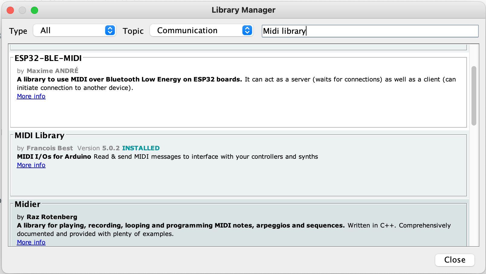
If you are having trouble finding the library, select “Communication” in the Topic dropdown. Apparently “midi” appears in the middle of lots of words, so you will likely get a ton of random results.
Now that we have the library installed, include it at the top of the .ino file:
#include <MIDI.h>Next, we need to create an instance of the MIDI object and tell it to listen to the correct Serial port (Serial2 in our case).
/*******************************************
 * MIDI Definition                         *
 *******************************************/

MIDI_CREATE_INSTANCE( HardwareSerial, Serial2, MIDI );
Handling MIDI Events
Now, we can define functions that handle incoming note on and note off events:
void handleNoteOn( byte channel, byte midiNote, byte velocity ){
  PROC_YM3812.chPlayNote( 0, midiNote );
}

void handleNoteOff( byte channel, byte midiNote, byte velocity ){
  PROC_YM3812.regKeyOn( 0, 0 );
}
Both of these functions receive the same arguments:
- channel: The MIDI channel of the incoming note
- midiNote: The pitch number of the note
- velocity: The volume of the note (for touch sensitivity)
In the handleNoteOn function, we simply use our play note function and pass the midi note number. For now, let’s keep this a mono-synth and play everything on channel zero of the YM3812.
In the handleNoteOff function, we (rather unsophisticatedly) tell channel zero to stop playing. There are a few issues with this, but we will address those when we make this thing polyphonic.
For these two functions to do anything, we need to register them with the MIDI Library. We do this by adding a few lines to the setup() function:
void setup(void) {
...

  //MIDI Setup
  MIDI.setHandleNoteOn(  handleNoteOn );
  MIDI.setHandleNoteOff( handleNoteOff );

  MIDI.begin();

...
}
setHandleNoteOn and setHandleNoteOff connect the functions we wrote above to the MIDI object. This way the MIDI object can run our function whenever it detects the associated event.
The begin function kicks things into gear and tells the MIDI library to start listening.
Listening for Events
Now that we have things set up, we need to regularly prompt the MIDI object to check for new information. We do this by modifying our loop function. If you still have all of the code from article 3, you can delete all of that and update the function to look like this:
void loop() {

  while( MIDI.read(0) ){}

}
The read function checks for any events related to the MIDI channel passed to it. If you pass a zero (as we did above) then it reacts to ALL incoming MIDI channels. When the read function detects an event, it initiates the associated handler function to manage that event and then returns true. If it does not detect an event it returns false. This way, by calling the function in a while loop, we ensure that we manage all captured events before moving on.
And with that, compile this puppy and send it up to the micro. With any luck, you should be able to control your YM3812 with an external MIDI keyboard, computer or really any midi device!
Some Things to Try
Once you have things up and running, try playing a note and then another note and then quickly release the first one. The issue becomes especially apparent if you set the properties of the voice to be more organ like. Take a look at the note-off function and see if there is something we can tweak to make things a bit more reliable.
A Few Final Thoughts
Having the ability to receive a midi signal and then play it on our YM3812 represents kind of a milestone. We now have something that functions as a playable instrument—even if that instrument has rather limited capabilities. Still, this was a necessary first step that lays a solid foundation for what’s to come. And in the next article, we will considerably enhance the capabilities of our device through polyphony. I guarantee it will become far more playable.


6 thoughts on “YM3812 Part 4 – MIDI Journey”
jc2046 (Spherical Sound Society)
I´ve spent the last weeks feverly working in projects that use the YM2413 (OPLL) and the YM262 (OPL3) chips. I even dream of the registers table. Yep, even working on it, I had a lot of holes in my understanding, specially on the bitwise operations, that are still enigmatic and hellish to me…
So, the equation of the previous post :
regVal = (regVal & (~(bitMask<<offset))) | ((newVal & bitMask) << offset))
And the associated macro
#define SET_BITS( regVal, mask, offset, newVal) ((regVal) = ((regVal) & (~((mask)<<(offset)))) | (((newVal) & (mask)) << (offset)))
And the crystal clear explanation is quite like a godsend. I will be heavily using it from now and probably your library too. So, thanks again for this delicious post entrances and sharing of your knowledge. Im enjoying every bit of it! 😀
Tyler in reply to jc2046 (Spherical Sound Society)
This totally made my day, thank you so much for the kind words! Let me know how the YM2413 ends up sounding. I got it working but it always had a hum in the background that I couldn’t get rid of. I figured it was the breadboard, but I had a YM3812 working on the same board too and it stayed very quiet. The YMF262 is an excellent chip, I’m sure you will do really awesome stuff with that one!
jc2046
Hi!
Im coming back to read it again and I find your answer one month later, lol 😀
Yeah, the 2413 is noisy as hell. You can look at my implementation in the arcane github but it has all kind of noises, digital noisettes filtering and probably the hum that you mention.
There´s also an enourmous variance in the chips per se. Some are extra noisy and other quite silent, so you get 5-10 chips, prepare a standard setup and check every chip, so you will find which ones behaves and which ones are belong directly to the recycle bin.
In my case the noise get way better once I used PCB instead of breadboard but it´s quite still there. Another thing that should work is to put resistors between the microcontroller and the 2413 lines. Prbably around 10-47k each to reduce currents. This should help with the digital noises. Also having a dedicated clean 5v regulator for it should help
For the opl3 Im using the Maarten Jansen PCB, that works flawlessly perfect. But The catch here is that Im exploring running emulators, from the MAME, inside PICO and ESP32 chips and after 2 months of delirium I have it running!. Impressive stuff. I got the inspirtion for the guy running DOOM on a pi pico. That´s guy is so next level:
https://github.com/kilograham/rp2040-doom
That is so full of pearls.
My emulators all glicth a lot and only run on overclocked PICO and on low sample rates (max 22000hz). The emus are written for PCs and it needs heavy optimizations and some assembler to more or less work.
Im starting to try with the ESP32 and it´s way better than the PICO. It does manage floats natively, so it get quite a performance boost, but Im still adapting drivers for it
Well, that´s it. I keep re-reading and studing your posts and videos. Top quality material.
Waiting for the coming posts. Cheers from Spanien 😀
jc2046
https://github.com/spherical-sound-society/ARCANE/blob/main/ARCANE_schematics.pdf
(Not a model, quite noisy as I told you, a lot of electrical optimizations are possible)