Introduction
In conducting a pretty extensive deep dive into Yamaha’s FM synthesis chips, I’ve come to realize that while these chips produce very unique sounds, they are also largely very similar. In fact, if you compare their register settings (and ignore the level of granular control that you get), you can see just how many of the settings are the same:
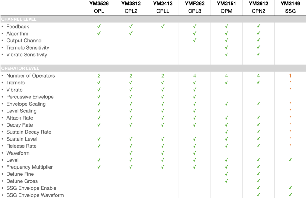
With all of these similarities in mind, I originally planned to build a single module with a variety of sound processor types all controlled by a single microcontroller. After breadboarding this idea out with a YM3812, YM2151 and even a non-Yamaha SN76494, it worked! And I was even able to translate chip settings from one chip to another seamlessly. But when I started to document how it worked, I realized from a complexity standpoint, I needed to back waaaay up and start from the beginning. To get into the advanced stuff, we need to start with a smaller project that lays a strong foundation. And what better foundation than a Eurorack module powered by Yamaha’s YM3812 OPL2 sound chip. A chip that revolutionized computer audio for the video games of my childhood.
This article is only the first in a series. Together, we will tour the properties of the YM3812, design the hardware for a module and write the supporting microcontroller code. Hopefully, each article will pair with a YouTube video on the subject as well.
Why the YM3812?
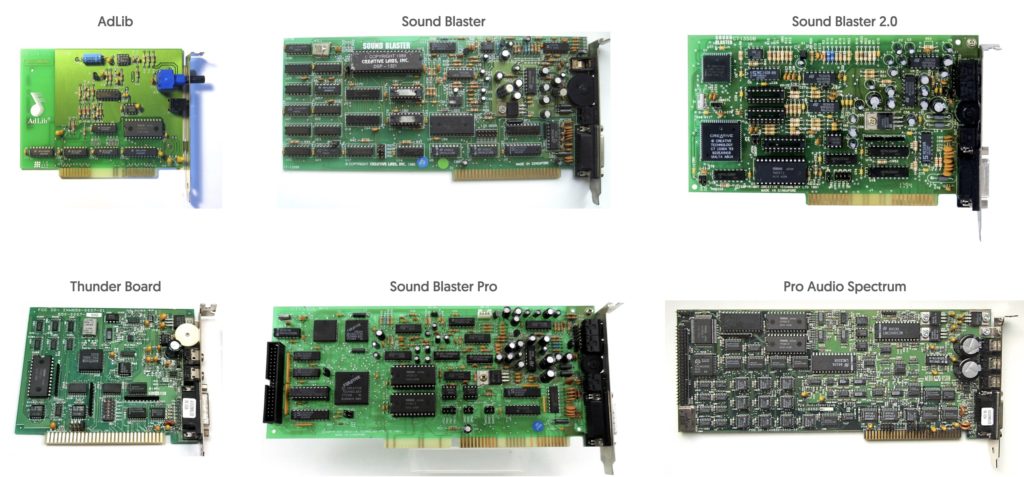
If you grew up in the 80’s and 90’s and played video games on a PC, then it is highly likely that you have listened to the glorious 8-bit audio output of a YM3812 sound processor. To me, this sound is synonymous with Sierra and Lucas Arts adventure games. I can still remember reading advertisements for the sound card in Sierra’s interAction magazine. The idea of getting music and sound effects other than square waves from a computer was like magic. So after saving up my dog-sitting money I bough a SoundBlaster Pro from Fry’s electronics. The first time using this thing was symphonic—it took adventure gaming to a whole new level. Now, 30-ish years later, I want to recapture that magic.
From a more practical standpoint, the YM3812 supports only two operators per voice making it significantly simpler to understand than other 4-operator or even 6-operator FM synthesizers. But don’t be fooled, this is still a powerful chip, capable of creating a vast variety of nostalgia-generating instrumental and percussion sounds—and that’s what makes this chip such a great starting point.
How does FM synthesis work on the YM3812?
Let’s start with a quick review of FM Synthesis and how sound processors use it to produce sound. The YM3812 is an FM Synthesis sound processor. It plays up to 9 different sounds (voices) simultaneously, with each sound composed of two different operators.
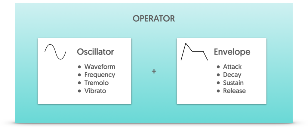
An operator is the basic building block of FM synthesis. It contains an oscillator that generates a sound wave, and an envelope that adjusts the sound’s level over time. Each voice of the YM3812 includes two of these operators, and they combine together using two possible algorithms:
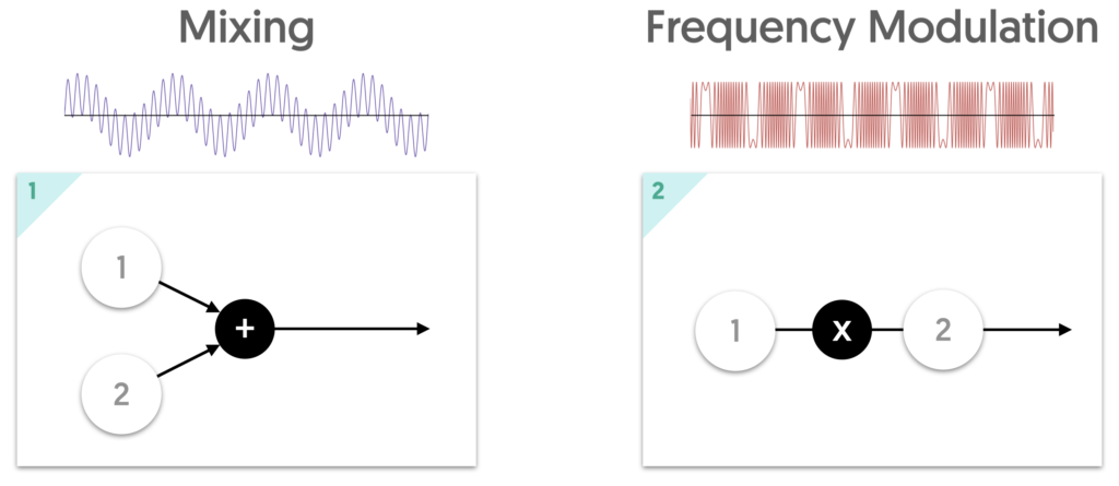
Mixing is the simplest form of “synthesis.” It adds the output of the two oscillators together like a mixer. In the output, both oscillators’ sounds are audible and distinct.
Frequency Modulation uses the first operator (called the modulator) to modulate the second operator (called the carrier). In this style, only the level of the carrier operator affects the level (volume) of the output signal. The level of the modulator operator affects the brightness of the timbre of the output. The higher the modulator level, the brighter the sound will be.
Frequency Modulation Demo
Words simply can’t do this justice, so let’s try a demonstration. I’ve connected an oscilloscope to the output of the final module (spoiler alert… the module eventually does work and this story will have a happy ending). I configured the module into Frequency Modulation mode and set the modulator operator to have a slowly decaying envelope. This way, you can hear how the amount of modulation changes the timbre of the sound as it slowly decreases. After playing a few notes, I also show how using different waveforms for the modulator and carrier signal also change the overall output.
Notice how the brightness quickly drops as the level of the modulating operator decays. In the Oscilloscope, it looks like the waveform collapses back into itself. Pretty cool right? Let’s try something even more mind bending…
Feedback
In the YM3812, the modulator operator (operator 1) also has the ability to modulate itself. What does that mean? This was incredibly difficult to wrap my head around, so I made an animation that starts with a sine wave and slowly increases the amount of feedback. As the amount of feedback increases, the waveform shifts from a sine wave into something more like a sawtooth wave. Then, after adding too much feedback, the wave deteriorates into inharmonic white noise. While less than musical, this white noise is a critical component of making percussive sounds on the YM3812, so it’s actually a good thing!

As an experiment to see if my animation aligns with reality, I plugged the final module into an oscilloscope. Now, we only want operator #1 because that is the operator that has the option for feedback. So, I set the module in mixing mode and turned the second operator’s signal all of the way down. This ensures that only the first operator’s signal appears in the output. I then set the first operator’s waveform to be a sine wave and then slowly increased the amount of feedback. You can see it shift from sine to saw… to crazy…
Types of Settings in the YM3812
The register settings that control sound production on the YM3812 fall into three different categories.
- Operator Level settings control how the oscillator and envelope functions. Oscillator settings include things like the waveform, detuning, and vibrato, while the envelope settings include things like attack, decay, sustain, and release. Operator settings have to be defined for every operator on the chip, so there are 18 sets of these settings on the YM3812.
- Channel level settings determine how the operators will work together to form a sound, as well as the things that affect that sound overall. Channel settings include the pitch of the note to play, whether the sound is turned on or off, and adding effects like tremolo and vibrato.
- Global level settings control the general properties of the chip like turning on “drum mode” or affecting internal chip timers. The “Deep Tremolo” and “Deep Vibrato” settings change the amount of vibrato / tremolo applied to the channels that have vibrato / tremolo enabled. Because these two settings are global, they affect all channels at once. As for the drum mode, you get 6 drum sounds for the cost of 3 channels. It seems like a good thing, but realistically you can achieve far superior drum sounds using normal instrument settings.
What are Registers?
In order to produce sound, the YM3812 uses a set of special-purpose memory locations to store the sound settings called registers. Because space comes at a premium, and there are so many different settings to store, the YM3812 compresses multiple settings into each register byte. So, for example, let’s say we found the value stored at register 0x41 to be 0x4C.
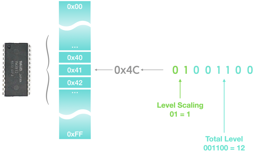
This value represents two different settings—Level Scaling and Total Level for Operator 1 of Channel 2. To understand how these values were combined, you have to look at the value of 0x4C in a binary representation. As shown above, this translates to a binary value of 01001100. The top bits on the left (the two “highest” bits) store the value “01” or in decimal, 1 and the next 6 bits store the value 001100 or in decimal, 12. The first number maps to the Level Scaling setting and the second to Total Level. Combining variables in this way saves memory because not every setting requires 8 bits to represent its value. Conversely, this also means that the maximum integer value a variable represents depends on the number of bits used.
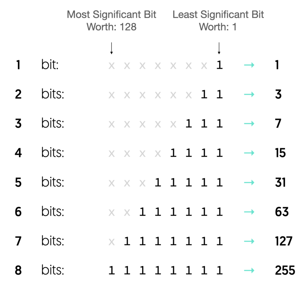
For example, a 1-bit number, can only be on or off, where as a 2-bit number can have 4 states (0-3). The number of allowable states doubles with each successive bit, until you get to a maximum of 256 (0 – 255) for an 8-bit number.
Note, the Frequency Number setting is the only one that uses MORE than 8 bits. This value is broken up across two register settings: an 8-bit Frequency Number LOW setting and a 2-bit Frequency Number HIGH setting. To combine these into a single 10-bit value, you shift the 2 high bits over to the left 8 times and then logically OR it with the low setting.
Finding Register Locations
Earlier, I pulled a random location 0x41 and somehow said, “oh that’s these two settings.” How the heck did I know that? Well, the answer is that I looked it up in the data sheet. But I think with a spreadsheet and a little information design, we can build a simple map to use going forward.
Global Registers

The chart above shows how settings map to the memory locations shown on the right. These 6 global registers scrunch together 18 different settings. The left side of the chart shows how the settings map to each bit of those 6 bytes. The D0 column represents the lowest bit in the byte and D7 represents the highest bit. So for example, if you wanted to set the Deep Vibrato flag’s setting, you take the current value of BD and do a logical OR with 0b01000000 to set the correct bit, and then write the result into the BD register.
Channel Registers

The channel-level registers follow a similar pattern, but with one added twist. Instead of each register type having one location in memory, they have 9—one for each channel. The columns on the left still indicate how bits map to settings, but now the columns on the right show the memory location of the register that corresponds to each channel. So, for example, if I wanted to turn sound generation on for Channel 5, I would have to set bit 5 of memory location 0xB4 to a 1, and that would play the note.
One more note, the base address column in the center provides the memory location of the first channel, and we can use it as an offset to calculate the other memory locations. So if we wanted the memory location of the “B0” setting of channel 5, we could find it with the formula, “0xB0 + 5 – 1”. The minus 1 is in there because the channel names are “1 indexed” instead of “0 indexed” If you labeled them channel 0 – 8, then “channel 5” would become “channel 4” and the formula would just be “0xB0 + 4”
Operator Registers

The operator-level register add a bit more complexity to the mix. I’ve laid them out in a similar fashion with the mapping of bits to setting types on the left and memory locations on the right, but now we have 18 different locations to contend with—one for each operator—instead of 9. For every channel, there are two operators—a Modulator and a Carrier. We can also abstract these into “Slot 1” and “Slot 2” because in other Yamaha chips, there are up to 4 operators per channel and numbers add clarity.
I’ve arranged the memory location columns in the table above to keep each operator visually connected with its associated channel. If you look closely, a curious pattern emerges. Channel 1 associates with operators 1 and 4, Channel 2 associates with operators 2 and 5, and so-on. The carrier operator number is always three higher than the modulator’s operator number.
In the chart above, the row below the operator numbers (that starts, “+0, +3, +1,…”) represents the memory offsets for each operator from the base address. So to find a memory location for a specific operator, you could add this value to the base address associated with the setting you want to change. Here again, there is another “gotcha.” The memory locations JUMP between channels 3 and 4, and skip offsets 0x6 and 0x7. A similar jump occurs between channels 6 and 7, where we skip offsets 0xE and 0xF as well. As far as I can tell, the easiest way to manage this is to put the offsets into an array that maps operator to memory location.
Full Register Map
If we put all of these pieces together, the full register map emerges:
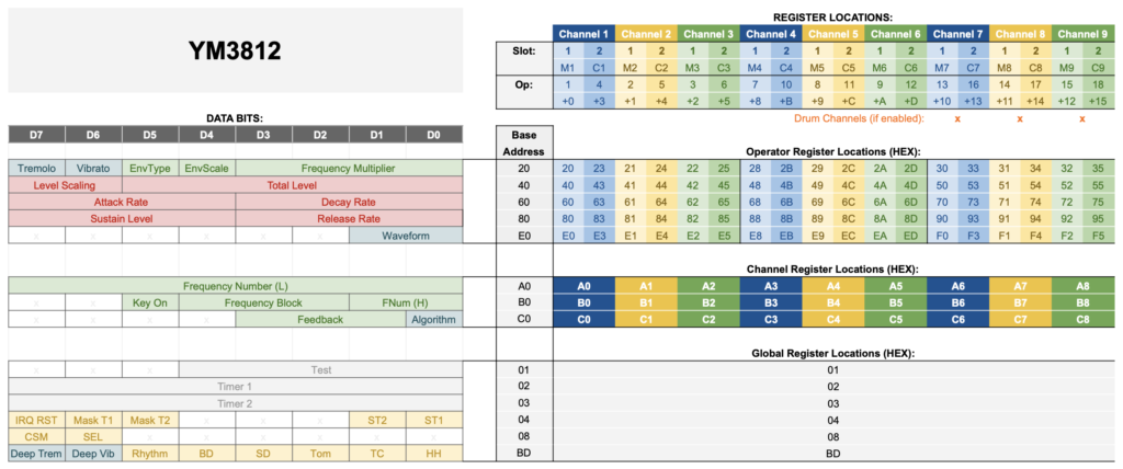
If you want to develop code that controls a YM3812, I highly recommend printing this chart, laminating it and pinning it to you wall. You are going to need it!
Oh, one other thing, if you turn on drum mode then channels 7, 8, 9 become dedicated to drum sound production. I’ve indicated this with orange asterisks in the chart above. Again, I’d recommend against using the default percussion sounds, but hey, it’s there if you need it!
Setting Registers on the YM3812
Now that we know the mapping of settings to register locations, let’s talk about how to set those registers… electrically.
YM3812 Pins
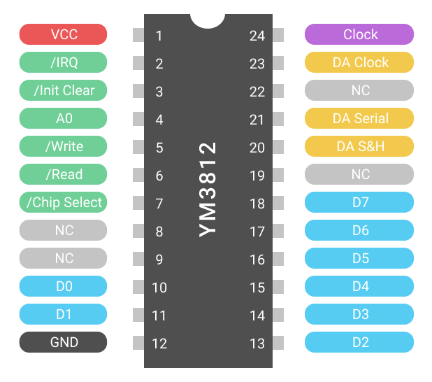
The pins of the YM3812 fit into three different types. The power pins connect to 5v and ground. The three pins in yellow provide a serial connection to the Y3014b digital to analog converter chip. The 8 pins in blue connect to the data bus, and the 6 green pins work as control lines. There are also a few unused pins in grey that we can ignore.
For this exercise, our interest lies in the 8 data lines and the A0, Write, and Chip Select control lines. The Init-Clear pin will clear the contents of the chips registers, and the IRQ and read pins are used to read status information from the chip. Unfortunately, you can’t read the contents of a register, so honestly reading information from the chip just isn’t that useful.
Selecting Registers & Sending Data
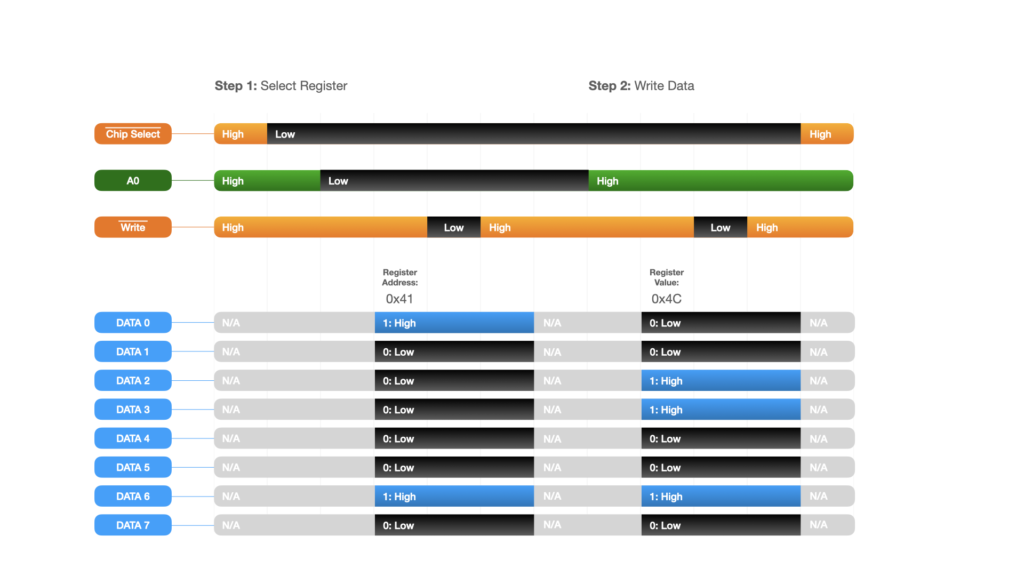
Setting the register requires two main steps: selecting the register, and setting its data. To select a register, we:
- Begin with the Chip Select and Write control lines high (disabled). The A0 line could be either high or low.
- Set the Chip Select line low to enable the chip
- Set A0 low to tell the YM3812 that we are selecting a register
- Put the address of the register we want to write onto the Data Bus
- Set Write to low to tell the YM3812 to use the data on the Data Bus to select the register
- Wait 10 microseconds
- Set Write to high to complete the write cycle
- Wait 10 microseconds. At this point the register is selected
- Flip the A0 control line high to indicate that we are now writing data into the register
- Put the value onto the Data Bus to write into the selected register
- Set Write to low to tell the YM3812 to write the data into the selected register
- Wait 10 microseconds
- Set Write to high to complete the write cycle.
- Wait 10 microseconds. At this point, the data has been written into the YM3812
- Set Chip Select back to high to disable the YM3812 again
And that’s it! If you followed the steps above, then you have written data into a register!
Wrap Up
Now that you know where all of the registers are on the chip, and how to manipulate them, you have the fundamental building blocks to control the YM3812. Of course getting from register setting to a working MIDI controlled module will require a bit more discussion. My hope is to take these topics one at a time in future articles. In the next article, let’s go through the module schematic, and after that we will get into some more software algorithms.



8 thoughts on “YM3812 Part 1 – Register Basics”
Wade
Great guide! Will be book marking this for future projects
Kesley Dempsey
Dude! I cannot tell you how excited for this project I am.. it’s like I’m knowing what you’re getting for Christmas and still having to wait for it to open your present. Thanks for all of great information and creating an exciting project for all of us sound nerd/fellow tinkerers out there.
Jianxin
Why set Chip Select to low to enable the chip? The datasheet said Chip Select to high to set data bus to high impedance.
Tyler in reply to Jianxin
Good question! Setting the chip select low enables the chip. The high impedance state is like the “off” state where the chip doesn’t interact with the bus.
marko
hi, great video. thanks for that. just a question regarding the bus interface and timings. from your presentation at 9:40 you explain that A0 is going low before CS. but from the ym3812 datasheet the timing diagram says, that CS must be driven low after the address (a0) is stable. this is t_as (address setup) 30ns (min), which means CS 30ns after A0. am i wrong?
currently i’, on debugging my sbc with ym3812… it works but the irq line is never driven low if a timer interrupt appears. the appropriate bits in status register are set, but from the hardware site. no irq line low at all :/ any ideas here?
Tyler in reply to marko
You are 100% correct——not sure how I missed that! The data sheet definitely says that you need to set A0 low first. There is a second version of the data sheet that is a bit more comprehensive (google: “YM3812 Manual”) and it goes into more details on the timing characteristics. It appears that tas has a minimum of 10ns and tah has a minimum of 20ns. So you should definitely set A0 before CS and clear it after CS. All that said… I have always set them the other way around without any issues (which is probably why I never caught this before!)
As for the IRQ, I’ve never actually used that feature. But, on page 23 of the application manual, they note that it has an open drain output. Are you using a pull-up resistor to keep the line high?
marko
hi, many thanks, also for pointing me to the app manual. yes, we have a pull-up resistor in place. we’ll see…. regards.
Pavel
This is great article!
How did you generate the sinus wave with feedback? Is the feedback just added into the input with some delay? Or does the actual amplitude change the “time delta”? (as – if I’m correct, the Yamaha chips performs phase modulation rather than fully FM).