The YM3812 Class
In the last article, we built a simple circuit to get our YM3812 up and running on a breadboard. To do that, we used code from the GitHub repo and just kind of glossed over how the it works. In this article, let’s delve into the sea of complexity that is c++ programming. Obligatory disclaimer: c++ is an incredibly flexible language with MANY ways of writing code from the simplest to the most enigmatic. I chose one way—not the best way, nor the simplest, nor the most elegant—just the way I thought to do it. If you have recommendations on how to improve the code, please leave a comment!
Code Structure
For now, the code resides in three files—though we will add a couple more before this project concludes:
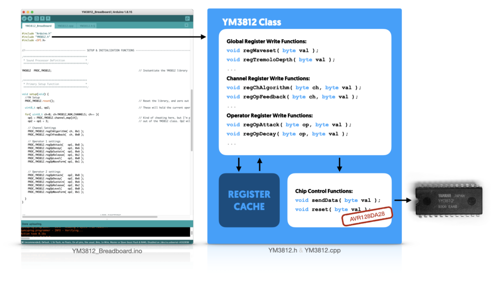
- YM3812_Breadboard.ino will be our primary “program”—that is, where the setup and main loop functions reside
- YM3812.h header file defines the YM3812 library that wraps the chip’s functionality into a class
- YM3812.cpp provides implementations for functions defined in the header file
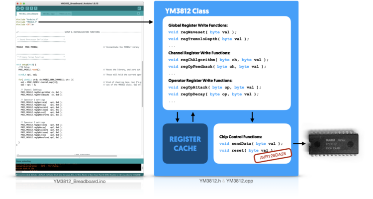
Inside of the YM3812 class are two different types of functions. The Chip Control Functions instruct the microcontroller to send data to (or reset) the YM3812. Their implementation depends entirely on the type of microcontroller used and how its pins are configured. The Register Functions utilize these Chip Control Functions to manipulate register settings in the YM3812. By coding things this way, if you want to use an Arduino or Teensy instead of the AVR128DA28, then you only need to change the sendData and reset functions. Everything else stays the same.
The last piece of our class is the Register Cache. Because we want to manipulate pieces of bytes in the registers at a bit level, we need to know the current state of all of the bits that we don’t want to change. The YM3812 doesn’t allow us to read registers on the chip, so instead, we have to store their current values in the microcontroller’s memory. At some point, we will discuss how to circumvent this, but that’s a few articles away.
Chip Control Functions
Let’s start with the lowest level functions that electrically manipulate the pins on the YM3812. The good news is that there are only two of them: sendData and reset.
sendData( reg, val )
If you read the first article, this should feel pretty familiar. sendData directly implements the timing diagram at the end of that article—but with one small change. “Putting data on the bus” requires sending the byte over SPI and then latching it onto the 74HC595. Let’s take a look:
//Port Bits defined for control bus:
#define YM_WR    0b00000001  // Pin 0, Port D - Write
#define YM_A0    0b00000010  // Pin 1, Port D - Differentiates between address/data
#define YM_IC    0b00000100  // Pin 2, Port D - Reset Pin
#define YM_LATCH 0b00001000  // Pin 3, Port D - Output Latch
#define YM_CS    0b00010000  // Pin 4, Port D - Left YM3812 Chip Select

...

void YM3812::sendData( uint8_t reg, uint8_t val ){
  PORTD.OUTCLR = YM_CS;     // Enable the chip
  PORTD.OUTCLR = YM_A0;     // Put chip into register select mode

  SPI.transfer(reg);        // Put register location onto the data bus through SPI port
  PORTD.OUTSET = YM_LATCH;  // Latch register location into the 74HC595
  delayMicroseconds(1);     // wait a tic.
  PORTD.OUTCLR = YM_LATCH;  // Bring latch low now that the location is latched

  PORTD.OUTCLR = YM_WR;     // Bring write low to begin the write cycle
  delayMicroseconds(10);    // Delay so chip completes write cycle
  PORTD.OUTSET = YM_WR;     // Bring write high
  delayMicroseconds(10);    // Delay until the chip is ready to continue

  PORTD.OUTSET = YM_A0;     // Put chip into data write mode

  SPI.transfer(val);        // Put value onto the data bus through SPI port
  PORTD.OUTSET = YM_LATCH;  // Latch the value into the 74HC595
  delayMicroseconds(1);     // wait a tic.
  PORTD.OUTCLR = YM_LATCH;  // Bring latch low now that the value is latched

  PORTD.OUTCLR = YM_WR;     // Bring write low to begin the write cycle
  delayMicroseconds(10);    // Delay so chip completes write cycle
  PORTD.OUTSET = YM_WR;     // Bring write high
  delayMicroseconds(10);    // Delay until the chip is ready to continue

  PORTD.OUTSET = YM_CS;     // Bring Chip Select high to disable the YM3812
}
The pin definitions at the top of the code provide a name for each pin of PORT D on the microcontroller. The sendData function then uses those definitions to directly manipulate the registers and turn on and off those pins.
If you are more accustomed to the digitalWrite() function on an Arduino, then OUTSET and OUTCLR might look a little strange. These map to registers in the AVR128DA28 microcontroller that directly manipulate the output pins. By writing a byte to OUTSET, any bits in that byte that are 1 will turn the corresponding pins on. Bits that are 0 will just be ignored. OUTCLR does the opposite. Any bits that are 1 in the byte will turn off their corresponding pins and, again, the 0s get ignored. While maybe a little less intuitive, directly manipulating these registers makes things MUCH faster.
Take note that in order for SPI.transfer() to work, you first have to run SPI.begin() at some point prior in the code. I got stumped by this bug while reducing the module code for this article. When I removed the code for the TFT screen—which also uses the SPI bus—the microcontroller locked up when it ran the SPI.transfer() function. This is because the TFT screen’s initialization function runs SPI.begin(). Once I added SPI.begin() to the YM3812’s reset function, everything worked perfectly!
void reset()
void YM3812::reset(){
  SPI.begin();                                            // Initialize the SPI bus

  //Hard Reset the YM3812
  PORTD.OUTCLR = YM_IC; delay(10);                        // Bring Initialize / Clear line low
  PORTD.OUTSET = YM_IC; delay(10);                        // And then high

  //Clear all of our register caches
  reg_01 = reg_08 = reg_BD = 0;                           // Clear out global settings
  for( uint8_t ch = 0; ch < YM3812_NUM_CHANNELS; ch++ ){  // Loop through all of the channels
    reg_A0[ch] = reg_B0[ch] = reg_C0[ch] = 0;             // Set all register info to zero
  }
  for( uint8_t op = 0; op < YM3812_NUM_OPERATORS; op++ ){ // Loop through all of the operators
    reg_20[op] = reg_40[op] = reg_60[op] = 0;
    reg_80[op] = reg_E0[op] = 0;                          // Set all register info to zero
  }

  regWaveset( 1 );                                        // Enable all wave forms (not just sine waves)
}
The reset function does four main tasks. First it initializes the SPI bus, then it hard-resets the YM3812 by bringing its reset line low and then high. The delays ensure the chip is ready before continuing. Third, it resets the register cache variables stored in the class to zero (so they match what should be in the chip now). And finally, it sets the “Waveset” flag to allow for all waveform types.
Twiddling Bits
The register functions build upon the chip control functions and follow a very similar pattern:
- Mask the new value to ensure it has the correct number of bits for the property you want to change
- Look up the current value of the register containing the property
- Erase the bits associated with the property that you want to overwrite
- Insert the masked property value‘s bits into the register
- Save the new combined register value into the register cache and send it to the YM3812
Bit manipulation turns out to be the most complicated part of this process. So let’s start with a macro that, once written, will allow us to tuck all of those details away and not worry about them any more:
SET_BITS( regVal, bitMask, offset, newVal )
This macro takes a register value (regVal) and combines a new property value (newVal) into it. The bitMask determines which of the bits from newVal to include, and offset determines where inside of regVal to insert those bits.

Looking at the left side of the chart above, we can see binary versions of newVal as well as bitMask. In this case, we want to insert a two-bit number into bits 4 and 5 of an existing register value without accidentally overwriting any of the other bits. A two-bit value should only ever have 1s in the lowest two bits, but of course, nothing prevents a developer from accidentally pushing a bigger value. So, to solve this, we use a bitMask that has 1s in the two lowest bits—the ones we want to keep—and then AND it with newVal. This way, we block out any rogue bits (like that 1 in red).
In order to insert those two bits into the current register value, we need to first set any bits we want to overwrite to zero. To create this “hole,” we shift the bitMask to the left by offset and then invert it (with the ~ operator). This puts a 1 in all of the bits we want to keep (as shown on the right side of the chart above). If we logically AND this new mask with regVal then those two bits will be zero.
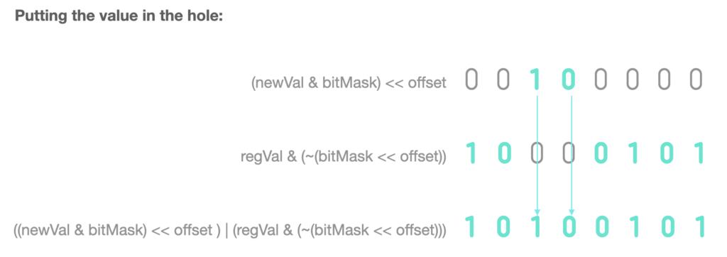
Now, to insert our trimmed newVal into the two bit hole in regVal, we need to shift the value over by offset so it is in the right spot. Then we just logically OR the repositioned value with the masked regVal and presto! We get a new regVal with newVal inserted into just the right spot, and without altering any other bits.
Representing this as a single formula looks something like this:
regVal = (regVal & (~(bitMask<<offset))) | ((newVal & bitMask) << offset))
In this case, regVal will be overwritten with the new combined value. And, because assigning one value to another returns the assigned value, you could wrap this entire thing in parenthesis and think of it like a function that both updates regVal and returns the updated value.
This is fairly complicated bit-math, so if its confusing, that’s OK. We are going to use this formula a lot though, so let’s tuck away all of that complexity into a macro:
#define SET_BITS( regVal, mask, offset, newVal) ((regVal) = ((regVal) & (~((mask)<<(offset)))) | (((newVal) & (mask)) << (offset)))Macros are a little like functions, except they aren’t executed at runtime. Instead, before compiling the code, the pre-compiler looks for any macro calls and replaces them with their associated code. For example, when the pre-compiler finds:
SET_BITS( reg_20[op], 0b00000001, 7, val )
It replaces that text with:
((reg_20[op]) = ((reg_20[op]) & (~((0b00000001)<<(7)))) | (((val) & (0b00000001)) << (4)))
We could write all of our functions without the macro using this expanded format, but personally, I find the first version easier to read. Also, we can combine this with our sendData function to write a single line of code for each of our register update functions. Let’s dive into those next.
Global Register Fns
Let’s put our sendData function and SET_BITS macro together to actually modify a register. There are three types of these register update functions—global, channel and operator. The Global registers are the simplest, so we’ll start there. Let’s write a function that sets the Tremolo Depth for the chip.

Looking at the Register Map, we see that the Deep Tremolo flag is located at bit B7 of register address 0xBD. To update this, we have to fetch the current value of register 0xBD from our register cache and then update bit B7.
What is this register cache? Well, there isn’t any way to read the current value of a register on the YM3812. So in order to update only a few bits of a register value, we need to keep track of the current values for all of the registers in memory on the microcontroller. Global registers only have one instance of their value, so they can be represented with integers. Channels and Operators both have multiple instances of their registers so we use integer arrays to store them. Here are the global register caches:
// Global Level Caches
uint8_t reg_01 = 0;  // Wave Select Enable
uint8_t reg_08 = 0;  // Speech Synthesis Mode / Note Select
uint8_t reg_BD = 0;  // Deep AM/VB, Rythm flag, BD, SD, TOM, TC, HH (Drum stuff)
As a convention, I’ve named each register cache variable after its base address. For global registers that have only one setting per base address, these are simply integers. Channel and Operator caches have multiple settings, so they are stored in arrays. Ok, let’s start piecing together our function.
void regTremoloDepth( uint8_t val ){ sendData( regAddress, value ); }We know that our function is going to call sendData to set the register value on the YM3812, and that the function requires both a register location and a value to set it to. regAddress comes from the chart above—0xBD—so that’s easy to fill in. value needs to combine the current value of our register cache with the val that was passed into the function. Good thing we have that SET_BITS macro, let’s pop that in:
void regTremoloDepth( uint8_t val ){
  sendData(0xBD, SET_BITS( regVal, bitMask, offset, newVal ) );
}
Filling in the blanks above, we first swap regVal for the variable containing the current value of the register we want to modify—reg_BD in this case. Then, because we are updating only a single bit, we swap bitMask for the constant, 0b00000001. Then, because the DeepTrem flag sits in bit 7, we swap offset for the constant, 7. Finally, we swap newVal for the variable that was passed into the function—val.
Here’s what the formula looks like once you make all of those changes:
void regTremoloDepth( uint8_t val ){
  sendData(0xBD, SET_BITS( reg_BD, 0b00000001, 7, val ) );
}
And there you have it, our one-liner function that allows the user to update the global tremolo depth value.
Channel Register Fns
Updating the channel registers works much the same way, but with one new wrinkle. Instead of one register per base address, we now have 9—one for each channel. Let’s look at the register caches to see how they are affected:
uint8_t reg_A0[YM3812_NUM_CHANNELS] = {0,0,0,0,0,0,0,0,0}; // frequency (lower 8-bits)
uint8_t reg_B0[YM3812_NUM_CHANNELS] = {0,0,0,0,0,0,0,0,0}; // key on, freq block, frequency (higher 2-bits)
uint8_t reg_C0[YM3812_NUM_CHANNELS] = {0,0,0,0,0,0,0,0,0}; // feedback, algorithm
Instead of simple integers, we use integer arrays to store our cache values. The arrays contain one integer for each of the 9 channels supported by the YM3812. This also means that in our register writing functions, we have to choose the correct register cache value based on the channel we want to update. Here is an example:
void regChFeedback( uint8_t ch, uint8_t val ){
  sendData(0xC0+ch, SET_BITS( reg_C0[ch], 0b00000111, 1, val ) );
}
This function modifies the feedback property of a specific channel. It takes two parameters: the channel to update and the value to set the feedback property to. Looking at our call to sendData, we see two important changes. First, we have to compute the address of the register we want to update by adding the channel number (ch) to the base address (0xC0). Second, we need to pull the correct register value from our cache by using ch as the array index.
Operator Register Fns
Updating operator registers works the same way as channels, but with yet another twist. The channel registers are all in sequence, so computing the register address is super simple (just add the channel number to the base address). We aren’t so lucky with the operators.

Operators 1, 2, 3, 4, 5, and 6 all pair with register offsets 0, 1, 2, 3, 4, and 5… so far so good. But then… Operator 7 pairs with register offset 8! what happened to 6 and 7? Then, later, we skip offset locations 0xE and 0xF. Woof.
To get around this, we use an array that maps the operator number to the memory offset:
uint8_t op_map[YM3812_NUM_OPERATORS] = { 0,1,2,3,4,5,8,9,10,11,12,13,16,17,18,19,20,21 };Let’s use the attack function as an example:
void regOpAttack( uint8_t op, uint8_t val ){
  sendData(0x60+op_map[op], SET_BITS( reg_60[op], 0b00001111, 4, val ) );
}
Now, instead of adding the operator number to the base address (like we did with channels), we add the mapped offset from our array.
All of the register functions follow these patterns, and when you put them together, they create a lovely and readable, almost table-like pattern:
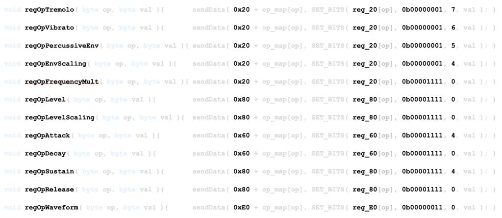
Really, the only things that change are the function name, the base address, the register cache, the bitMask and the offset. And, of course, all of those values come from the Register Map.
For the full implementation of all of these functions, check out the GitHub repot. This version has been heavily simplified to match this article and will serve as a foundation for all of the other functionality we’ll be adding.
Making Music
The time has finally come… Let’s go back to our YM3812_Breadboard.ino file and put our library to good use. Again, we are going to keep this as simple as possible. There are two parts: setting things up in a setup() function, and then playing a sequence of notes in a loop() function.
setup()
The first thing we need to do is initialize the YM3812 library. I’ve defined a global instance of the library with the line:
YM3812 PROC_YM3812Then, inside of the setup function, we initialize the library with the reset function:
PROC_YM3812.reset();At this point, we get to set up the properties of the sound that we want to create. To keep this simple, let’s just tell every channel to have the same sound properties:
//Set up a patch
for( uint8_t ch=0; ch<YM3812_NUM_CHANNELS; ch++){   // Use the same patch for all channels
  op1_index = PROC_YM3812.channel_map[ch];
  op2_index = op1_index + 3;                        // Always 3 higher

  //Channel settings
  PROC_YM3812.regChAlgorithm(  ch, 0x1 ); // Algorithm (Addative synthesis)
  PROC_YM3812.regChFeedback(   ch, 0x0 ); // Feedback

  //Operator 1's settings
  PROC_YM3812.regOpAttack(   op1_index, 0xB );
  PROC_YM3812.regOpDecay(    op1_index, 0x6 );
  PROC_YM3812.regOpSustain(  op1_index, 0xA );
  PROC_YM3812.regOpRelease(  op1_index, 0x2 );
  PROC_YM3812.regOpLevel(    op1_index, 0x0 );      // 0 - loudest, 64 (0x40) is softest
  PROC_YM3812.regOpWaveForm( op1_index, 0x1 );

  //Operator 2's settings
  PROC_YM3812.regOpAttack(   op2_index, 0xB );
  PROC_YM3812.regOpDecay(    op2_index, 0x6 );
  PROC_YM3812.regOpSustain(  op2_index, 0xA );
  PROC_YM3812.regOpRelease(  op2_index, 0x2 );
  PROC_YM3812.regOpLevel(    op2_index, 0x0 );      // 0 - loudest, 64 (0x40) is softest
  PROC_YM3812.regOpWaveForm( op2_index, 0x1 );

}
As we loop through the channels, we have to first compute the index of the operators we want to modify. And of course, it’s quirky. Operator 2‘s index will always be 3 higher than Operator 1‘s. The pattern for Operator 1‘s index however, is less straightforward. To get around this, we are going to add another array to our YM3812 class that maps from channel number to its associated Operator 1 index:
uint8_t channel_map[YM3812_NUM_CHANNELS] = { 0,1,2,6,7,8,12,13,14 };Now that we know which channel to modify as well as the associated operator indexes, the rest of the function configures each of the sound parameters using the register functions.
Loop()
Now finally, we get to play the four notes in our chord. And there are just a few steps to do it:
First, we turn off any notes that might happen to be on:
  PROC_YM3812.regKeyOn(  0, false ); //Turn Channel 0 off
  PROC_YM3812.regKeyOn(  1, false ); //Turn Channel 1 off
  PROC_YM3812.regKeyOn(  2, false ); //Turn Channel 2 off
  PROC_YM3812.regKeyOn(  3, false ); //Turn Channel 3 off
Then we set the octave we want the notes to be in:
  PROC_YM3812.regFrqBlock( 0, 4); //Fourth Octave
  PROC_YM3812.regFrqBlock( 1, 4); //Fourth Octave
  PROC_YM3812.regFrqBlock( 2, 4); //Fourth Octave
  PROC_YM3812.regFrqBlock( 3, 4); //Fourth Octave
Then we set the frequency for each of the notes:
  PROC_YM3812.regFrqFnum( 0, 0x1C9 ); // F
  PROC_YM3812.regFrqFnum( 1, 0x240 ); // A
  PROC_YM3812.regFrqFnum( 2, 0x2AD ); // C
  PROC_YM3812.regFrqFnum( 3, 0x360 ); // E
Wait… 0x1C9, 0x240, 0x2AD and 0x360 look nothing like F A C E… Nothing to see here… we will talk about that in the next article. Anyway… Finally, we turn the notes on:
  //Turn on all of the notes one at a time
  PROC_YM3812.regKeyOn(  0, true );
  delay(100);
  PROC_YM3812.regKeyOn(  1, true );
  delay(100);
  PROC_YM3812.regKeyOn(  2, true );
  delay(100);
  PROC_YM3812.regKeyOn(  3, true );
  delay(1000);
Now, I turned all of the notes on one at a time here by adding delays, but if you remove those, they would turn on all at once.
Final Thoughts
My goodness that was a long article. Apparently “FACE reveal” is a bit more involved than “hello world.” If you made it all of the way through, I hope that a lovely F Major 7th chord is echoing through your speakers at this very moment. If you ran into any trouble along the way, feel free to post questions in the comments. All of the working code is posted on gitHub, so hopefully that will help you in the troubleshooting process as well.
While the journey so far may have been arduous, it’s just getting started. Remember how I glossed over the frequencies for F A C E? Well, if we want to add midi control we are going to need a way to translate midi notes into those values. You know all of those register control functions we made? Eventually we are going to get rid of most of those—there’s a better way. But for now, don’t worry about all of that. Enjoy the fruits of your labor. See if you can create more interesting instruments than the one I used. Maybe program in a nice little jig! You got this.
In the next article, we’ll add midi control.
