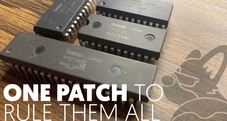
A couple years ago, I had this crazy idea of controlling multiple Yamaha FM sound chips with a single microcontroller. At the time, I had a YM3812, YM2151, YM2413 and even a non-Yamaha chip, the SN76489 on a breadboard outputting sound together. It turned out that controlling the chips themselves wasn’t really that hard. They all follow generally the same principles that we have been using to control the YM3812. The tricky part turned out to be finding a way to control the sound properties in an even remotely consistent way. Each of the chips has different properties, and those properties have different ranges. Those differences became pretty impossible to keep track of in my head, which began my quest to find a unified way of controlling them.
If you’ve been following along through the blog over the last few months, I’m building a EuroRack module around the YM3812 OPL2 sound processor. In the last entry, we got our module running with 9 voice polyphony and that made it a pretty playable instrument. Still, to change the characteristics of the sound itself, you have to set all of the sound properties one at a time. In this article, we are going to fix that by bringing together all of the settings into a single data structure called a patch. But this patch isn’t just going to work for the YM3812, it’s going to be cross compatible with several Yamaha sound processors. Moreover, we are going to explore how to assign different MIDI channels to different patches. This will allow us to use multiple patches at the same time and turn our instrument into an orchestra! Let’s get started.
A Unified Patch Structure
Over the years Yamaha produced a variety of sound chips, each with its own unique set of features. Now to keep this exercise reasonably simple, I’m going to focus on a subset of the chips that use four operators or less. Within this list, there are some interesting familial relationships between the chips.
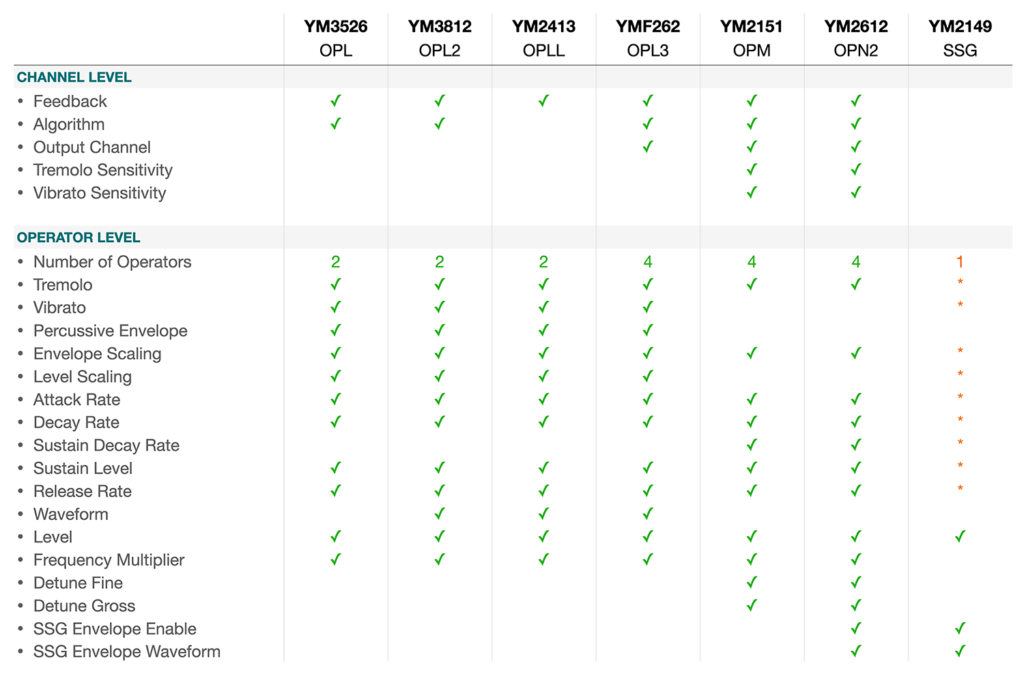
Yamaha Chip Evolution
The YM3526 (OPL) was the first in the OPL family of sound processor. It combined sine waves through frequency modulation to produce a wide variety of sound characteristics and represented a radical departure from the square-wave chips at the time.
The YM3812 (OPL2) added multiple waveforms, but otherwise stayed much the same. In fact, this chip is backwards compatible with the YM3526 and you actually have to take it out of compatibility mode in order to use the broader waveform set.
Yamaha introduced the YM2413 (OPLL) as a budget version of the YM3812 designed for keyboard usage. This chip comes with a set of pre-configured instruments as well as a user-configurable one. You can only use one instrument at a time—which makes sense for a keyboard. The chips have a built in DAC, but I have found the audio to be rather noisy.
The YMF262 (OPL3) advanced the OPL family considerably by upping the number of operators per voice to 4, adding even more waveforms, and—assuming you spring for two DAC chips—up to four output channels. Still, even this chip is backwards compatible all the way to the YM3526.
While the YM2151 (OPM) launched in 1984 around the same time as the YM3526, this family of sound chips departed from the OPL family in a few key ways. For one, this chip started out with four operators per voice, but did not include additional waveforms beyond sine waves. This chip provided a more advanced low frequency oscillator (that support multiple waveforms) and the ability to change tremolo/vibrato levels at the individual channel level. The OPM line also introduced detuning and an alternative style of envelope generation.
The YM2612 (OPN2) builds on the functionality of the YM2151, adopting its 4-op sine-wave-only approach to FM synthesis. This chip removes some of the LFO and noise-generation capabilities of the YM2151, but also adds a DAC as well as SSG envelopes.
Envelope Differences

The OPL family provides two different envelope types that you can select through the “Percussive Envelope” setting. In a percussive envelope, the release cycle begins as soon as the decay cycle ends. This allows you to create percussive instruments like drums, xylophones, wood blocks, etc.
The OPM/N family provides only one envelope type, but adds a new setting called Sustain Decay. With this setting you can create both ADR and ADSR envelope styles as well as anything in between.

SSG envelopes control the channel level in a repeating envelope pattern according to the chart above. The AY-3-8910 introduced this feature in 1978. Later, Yamaha picked up manufacturing of this chip with a couple tweaks and rebadged it as the YM2149 (SSG). These three-voice chips produce sound with square waves and don’t use FM synthesis at all. Still the SSG envelope has a very distinctive sound and it’s interesting to see them reappear as a feature in the YM2612 (OPN2).
Lastly, it’s worth noting that while chips like the YM2149 and the SN76489 don’t provide envelopes or LFOs, you can emulate them by using a microcontroller to adjust the level directly. Maybe a good topic for a future article? 🤔
Comparing Property Ranges
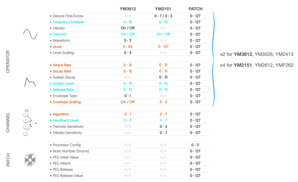
Of course the differences between these chip families differ at more than a feature level. Once you look at the range of values each property supports, their familial relationships become even clearer:
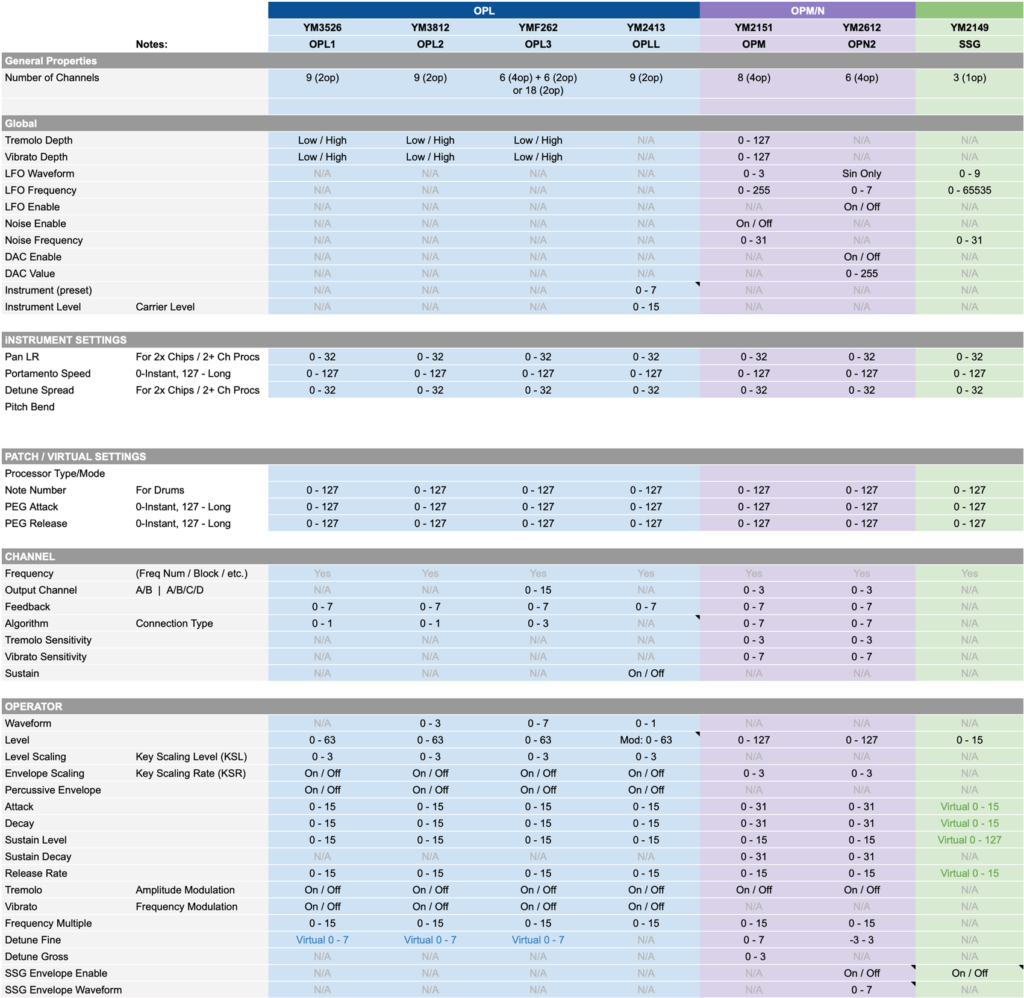
Ignoring the YM2149 for a second, the major differences between the chips coincide around the two chip families (the OPL vs. OPM/N). The OPM/N family provides more granular control over the attack and decay envelope settings (0..31 vs. 0..15), level (0..127 vs. 0..63), and envelope scaling (0..3 vs. 0..1). With more operators, the OPM/N family also allows a wider range of values for algorithm (0..7 vs. 0..1). Even the 4-op YMF262 (OPL3) only provides 4 algorithms.
In order to produce a patch that works across these chips, we need a way to represent these ranges consistently. And to do that we’ll review a little bit math. If you recall from the first article, each register byte combines multiple settings by dedicating a few bits to each one.

The maximum values derive from the limited number of bits associated with each setting. The more bits, the broader the range, and every maximum is a multiple of two.
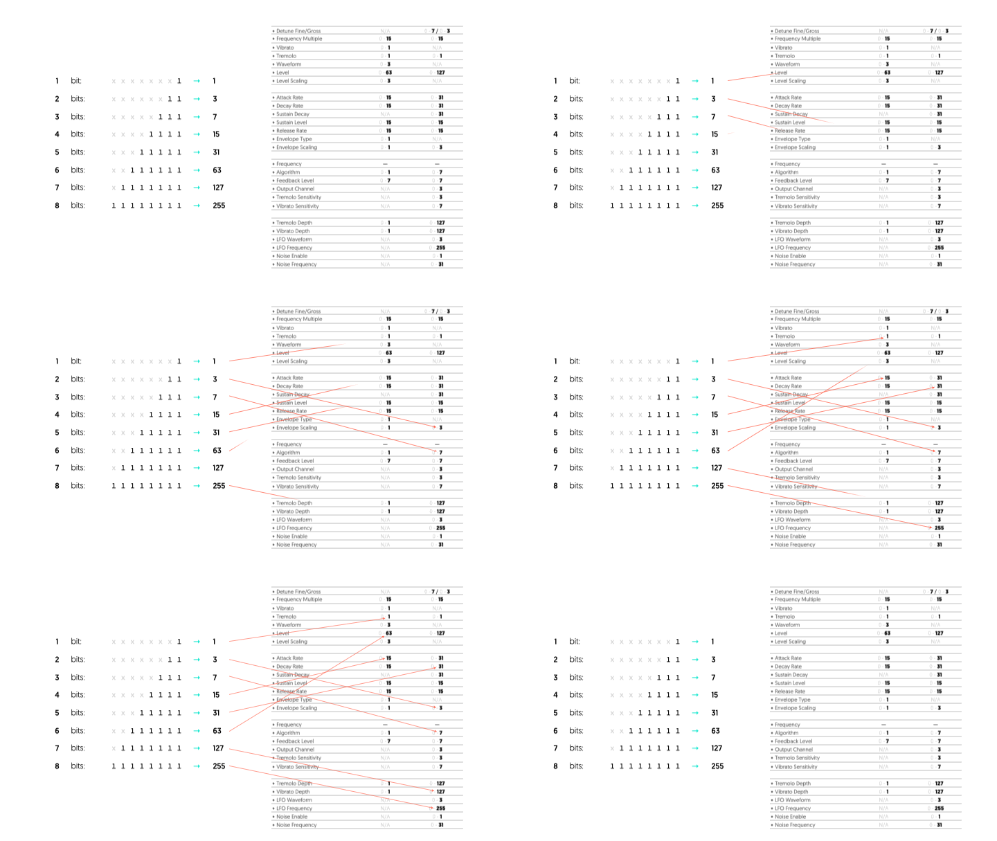
With this in mind, scaling settings between different chips could be as simple as left or right shifting the value. For example, Attack on the YM2151 ranges from 0-31 (a 5-bit number), while Attack on the YM3812 ranges from 0-15 (a 4-bit number). So if you had a YM3812 attack value, you could scale it for the YM2151 by shifting the number one bit to the left. This is equivalent to multiplying the number by two. Unfortunately, we always loose fidelity when we scale a number down and back up. For example:
(19 >> 1) << 1 == 18 (not 19)
Finding Consistency
We solve this by only scale numbers down, and never back up. This means we have to start with the largest possible value and scale down from there. By default, the MIDI specification allows values that range from 0-127. You can send larger values, but need to break them up across multiple bytes. Thankfully, this range covers nearly all of the values we’d need anyway, so it’s a good place to start. With this in mind, I updated the combined spec:
Non-patch settings
Most of the operator-level and channel-level settings make sense to include in the patch because they alter the properties of the sound. However, settings like frequency and output channel are more “runtime” properties. They affect things like the note you are playing and the speaker you are playing it through. Additionally, global settings like Tremolo Depth change all patches being played on the system at the same time. So, if you reassigned those every time you loaded a patch, those patches would conflict and override each other. For this reason, global settings can’t be included in the patch either.
Adding a few extras
Processor Config associates the patch with a sound processor type. Since our module only includes a YM3812 chip, we can ignore this setting for now. For a multi-sound processor module though, this would become super important.
Note Number indicates the note frequency to use when playing percussion sounds. We will dig more into this with the next article, but MIDI channel 10 aligns to a dedicated percussion mode. In this mode, each note on the keyboard aligns to a different patch, providing access to 42 different drum sounds. Of course those percussive sounds still need to be played at a specific frequency. And since we can’t rely on the keyboard key for that frequency, we use the note number setting instead.
Pitch Envelopes (PEG)
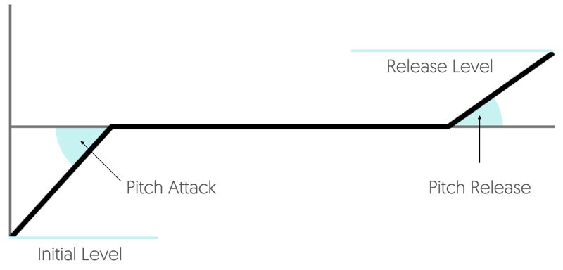
This one is a bit of a stretch goal for me. Pitch envelopes—like other envelopes—trigger upon playing a note. But, instead of affecting the sound level, they bend the pitch into the note while it’s held, and then away from the note upon release. You can find this feature on sample-based modules like Yamaha’s MU series, but not in these FM chips. To make this work, we will have to emulate the functionality in the micro-controller. For now, I’ve added it to the spec as a placeholder.
Coding the Final Spec
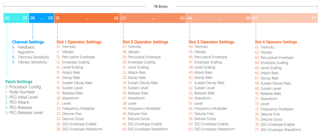
Putting everything together, we get a 78 element array of 8-bit integers. Each element of this array corresponds to an index shown above. The first 10 elements store the general patch & channel settings, while the remaining elements store operator settings in groups of 17. Since there are four operators, you can calculate the full patch size by multiplying the number of operator settings by 4 and adding the number of general settings.
I’ve defined these values in a new file called, YMDefs.h:
#define PATCH_GEN_SETTINGS    10
#define PATCH_OP_SETTINGS     17
#define PATCH_SIZE            PATCH_GEN_SETTINGS + PATCH_OP_SETTINGS * 4
Also in the YMDefs.h file, the PatchArr data type defines the patch structure. It is simply an array of 8-bit integers:
typedef uint8_t PatchArr[PATCH_SIZE]; // Define the PatchArr type as a uint8_t array
Additionally, I’ve added definitions for every array index. Each setting includes comments that show the supported sound processor types.
// Instrument Level / Virtual
#define PATCH_PROC_CONF        0 // Specifies the processor and desired processor configuration
#define PATCH_NOTE_NUMBER      1 // Indicates the pitch to use when playing as a drum sound
#define PATCH_PEG_INIT_LEVEL   2 // Initial pitch shift before attack begins (Virtual setting - none of the YM chips have this by default)
#define PATCH_PEG_ATTACK       3 // Pitch Envelope Attack (Virtual setting - none of the YM chips have this by default)
#define PATCH_PEG_RELEASE      4 // Pitch Envelope Release (Virtual setting - none of the YM chips have this by default)
#define PATCH_PEG_REL_LEVEL    5 // Final Release Level (Virtual setting - none of the YM chips have this by default)

// Channel Level
#define PATCH_FEEDBACK         6 // Used by: YM3526 | YM3812 | YMF262 | YM2413 | YM2151 |        | YM2612 |
#define PATCH_ALGORITHM        7 // Used by: YM3526 | YM3812 | YMF262 |        | YM2151 |        | YM2612 |
#define PATCH_TREMOLO_SENS     8 // Used by:        |        |        |        | YM2151 |        | YM2612 | *SN76489
#define PATCH_VIBRATO_SENS     9 // Used by:        |        |        |        | YM2151 |        | YM2612 | *SN76489

// Operator Level
#define PATCH_WAVEFORM        10 // Used by:        | YM3812 | YMF262 | YM2413 |        |        |        |
#define PATCH_LEVEL           11 // Used by: YM3526 | YM3812 | YMF262 | YM2413 | YM2151 | YM2149 | YM2612 | *SN76489
#define PATCH_LEVEL_SCALING   12 // Used by: YM3526 | YM3812 | YMF262 | YM2413 |        |        |        |
#define PATCH_ENV_SCALING     13 // Used by: YM3526 | YM3812 | YMF262 | YM2413 | YM2151 |        | YM2612 |
#define PATCH_PERCUSSIVE_ENV  14 // Used by: YM3526 | YM3812 | YMF262 | YM2413 |        |        |        | *SN76489
#define PATCH_ATTACK          15 // Used by: YM3526 | YM3812 | YMF262 | YM2413 | YM2151 |        | YM2612 | *SN76489
#define PATCH_DECAY           16 // Used by: YM3526 | YM3812 | YMF262 | YM2413 | YM2151 |        | YM2612 | *SN76489
#define PATCH_SUSTAIN_LEVEL   17 // Used by: YM3526 | YM3812 | YMF262 | YM2413 | YM2151 |        | YM2612 | *SN76489
#define PATCH_SUSTAIN_DECAY   18 // Used by:        |        |        |        | YM2151 |        | YM2612
#define PATCH_RELEASE_RATE    19 // Used by: YM3526 | YM3812 | YMF262 | YM2413 | YM2151 |        | YM2612 | *SN76489
#define PATCH_TREMOLO         20 // Used by: YM3526 | YM3812 | YMF262 | YM2413 | YM2151 |        | YM2612
#define PATCH_VIBRATO         21 // Used by: YM3526 | YM3812 | YMF262 | YM2413 |        |        |
#define PATCH_FREQUENCY_MULT  22 // Used by: YM3526 | YM3812 | YMF262 | YM2413 | YM2151 |        | YM2612 |
#define PATCH_DETUNE_FINE     23 // Used by:        |        |        |        | YM2151 |        | YM2612 | *SN76489
#define PATCH_DETUNE_GROSS    24 // Used by:        |        |        |        | YM2151 |        | YM2612 | *SN76489
#define PATCH_SSGENV_ENABLE   25 // Used by:        |        |        |        |        | YM2149 | YM2612 | *SN76489
#define PATCH_SSGENV_WAVEFORM 26 // Used by:        |        |        |        |        |        | YM2612 | *SN76489
Now, to access a value inside of a PatchArr object—let’s say you had one called, “patch”—you can use these defined indexes. For example:
patch[PATCH_FEEDBACK] = 27;
To access a specific operator’s setting, you need to add on PATCH_OP_SETTINGS times the operator number that you want—assuming the operator numbers go from 0 to 3:
patch[PATCH_ATTACK + PATCH_OP_SETTINGS * opNumber] = 18;
Assigning Patches to Channels
Now that we have our patch structure, we need to decide how and when to send the patch information to the YM3812. This part of the project threw me for the biggest loop. So, just in case you get my same bad idea, I’ll show you where I went off the rails.
Partitioning YM3812 Channels
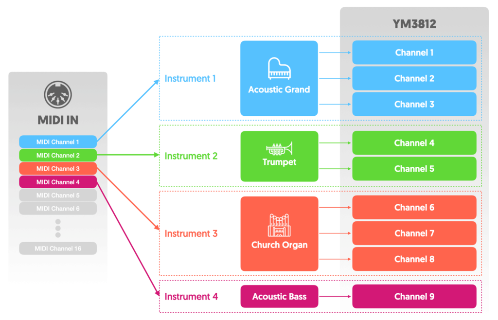
First, partition the YM3812’s nine channels into sets of channels that each represent an “instrument.” Then, depending on the assigned instrument, upload the appropriate patch information. Now that everything is configured, listen to the different MIDI input commands and—depending on the MIDI channel number—direct the play note functions to the appropriate set of channels.
In this configuration, each set of channels becomes its own polyphonic instrument. But the more instruments you have, the fewer voices each instrument can support. In fact, if you had 9 instruments, they would all be monophonic. Clearly, to support 16 MIDI channels, we are going to have to do this in another way…
Dynamic Patch Reassignment
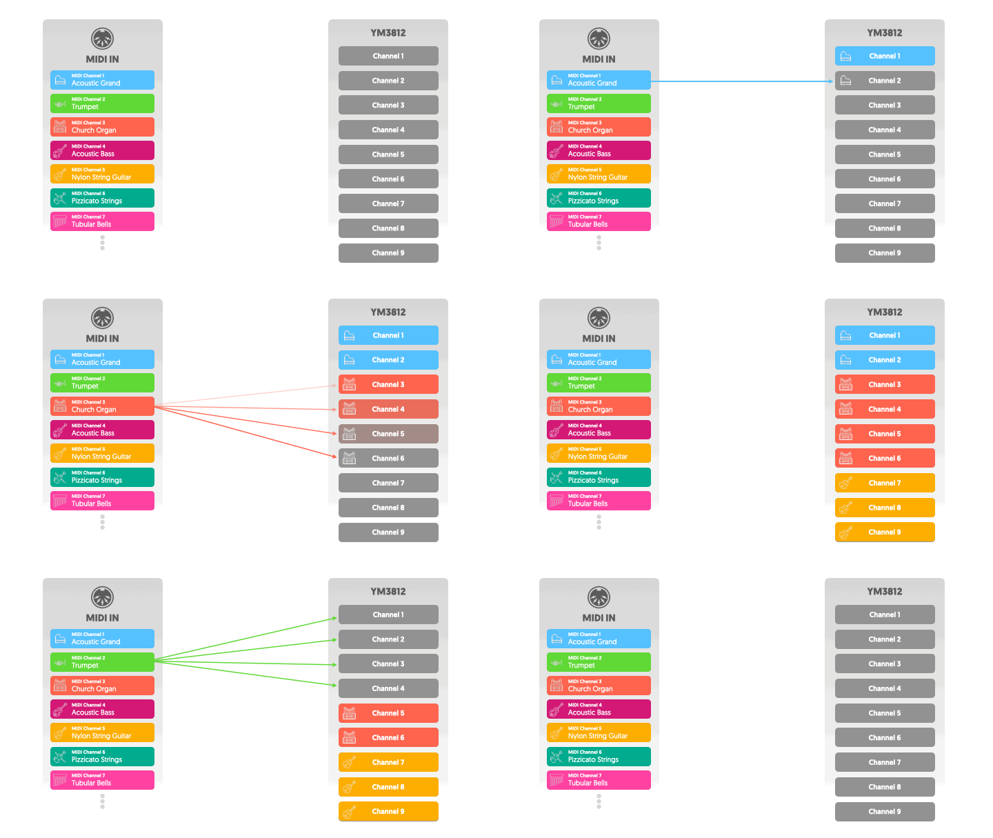
The assumption that led me to partition the channels was that uploading patch information takes too long. Thus, I assumed that it should only occur once during setup—before receiving note information. Let’s set that assumption aside for a moment and see what happens if we reassign voices on the fly.
In this new model, we associate our instrument patches with MIDI channels. When we receive a note, we choose a YM3812 channel using our normal polyphonic algorithm. Then, we can upload the associated patch information to the channel, and finally play the note.
There are several key advantages to this algorithm:
- It supports different instruments for every MIDI channel. While it’s true that only nine notes can be played at once, those notes could come from any number of different instruments. By associating a patch with each MIDI channel, we can support a different instrument for each of the 16 MIDI channels.
- It supports up to nine-voice polyphony: Even with 16 different instruments, each instrument can play up to 9 notes—just not all at once. We don’t have to decide up front how much polyphony each instrument gets.
- We never need to know what’s on the YM3812: Because we keep overwriting the sound properties on the chip, we never really need to know what’s on it. Thus, we don’t need to track all of the register values, and that saves a good bit of RAM.
Testing Reassignment Speed
But what about the disadvantage? Can we really upload a new patch every time we play a note?
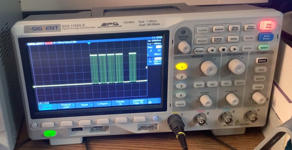
Here I played 5 notes and monitored the debug LED that flashes during the SendData command. Each horizontal division represents 1 millisecond. So, each note takes approximately 1ms to send. During my experimentation, I really tried to play all 5 notes at exactly the same time. And yet, as you can see, there is still a gap between the 4th and 5th notes. Clearly, human time just isn’t the same as computer time.

With this in mind, let’s look at the worst possible case of playing 9 notes at the same time. It takes 9ms to update every patch on the YM3812 and turn the notes on. At 120BPM, that’s about 7% of a 16th note. Math aside, if there’s a delay, I honestly can’t seem to notice it.
YM3812 Library Updates
Sending all of the patch data at once, requires a fundamental rearchitecting of our YM3812 class.
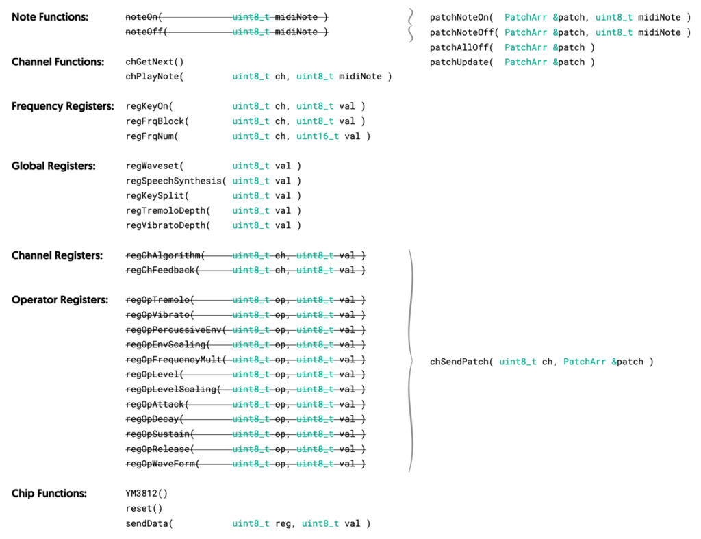
Replacing Register Functions
First, we replace our Channel and Operator register functions with a single “chSendPatch” function. Yes, this change eliminates a lot of the work we’ve put into the module to date. But, it also provides us with a TON of flexibility. Whether you code the chSendPatch to interface with a YM3812 or a YM2151, you call the function the same way. You pass the same patch object, and use the same 0..127 ranges for all properties.
Let’s have a look at how the chSendPatch function works:
void YM3812::chSendPatch( byte ch, PatchArr &patch ){
  byte mem_offset, patch_offset;

  //Channel Settings
  sendData( 0xC0+ch,  ((patch[PATCH_FEEDBACK]>>4)<<1) | ((patch[PATCH_ALGORITHM]>>6)<<0) );

  //Operator Settings
  for( uint8_t op = 0; op<2; op++ ){

    mem_offset = op_map[channel_map[ch] + op*3];
    patch_offset = PATCH_OP_SETTINGS * op;

    sendData( 0x20+mem_offset,      ((patch[patch_offset+PATCH_TREMOLO        ]>>6)<<7)  | ((patch[patch_offset+PATCH_VIBRATO      ]>>6)<<6) |
                                    ((patch[patch_offset+PATCH_PERCUSSIVE_ENV ]>>6)<<5)  | ((patch[patch_offset+PATCH_ENV_SCALING  ]>>6)<<4) |
                                    ((patch[patch_offset+PATCH_FREQUENCY_MULT ]>>3)<<0)  );

    sendData( 0x40+mem_offset,      ((patch[patch_offset+PATCH_LEVEL_SCALING  ]>>5)<<6)  |  (patch[patch_offset+PATCH_LEVEL        ]>>1)     );
    sendData( 0x60+mem_offset,      ((patch[patch_offset+PATCH_ATTACK         ]>>3)<<4)  | ((patch[patch_offset+PATCH_DECAY        ]>>3)<<0) );
    sendData( 0x80+mem_offset, ((0xF-(patch[patch_offset+PATCH_SUSTAIN_LEVEL  ]>>3))<<4) | ((patch[patch_offset+PATCH_RELEASE_RATE ]>>3)<<0) );
    sendData( 0xE0+mem_offset,      ((patch[patch_offset+PATCH_WAVEFORM       ]>>5)<<0)  );
  }
}
This function takes our generic patch and repackages all of the properties into YM3812 register values. Then, it takes those register bytes and uploads them to the chip. To repackage those properties, this function:
- Scales the property from the 0..127 range to the range appropriate for the setting by right shifting the value
- Aligns the new value to the correct bits in the register map by left-shifting
- ORs together the values that go into the same register byte
- Uploads the combined byte to the YM3812 using the sendData function
If you need to brush up on how the formulas above calculate the register addresses, take a look at article #3 of the series.
Calculating the index of each setting in the patch works just like we discussed earlier in the article. We used a named index like, “PATCH_FEEDBACK” to locate the correct setting in the patch array. And for operator settings, we add on PATCH_OP_SETTINGS multiplied by the operator number we want to edit. By cycling through the operators in a for loop, we can easily calculate a patch_offset and just add it onto the name of the setting we want to edit.
This looping structure scales up nicely for the YM2151 that has four operators. You just change the loop to go from 0..4 instead of 0..2. In fact, take a look at the same function written for the YM2151. Pretty similar, eh?
void YM2151::chSendPatch( byte ch, PatchArr &patch ){
  byte mem_offset, patch_offset;

  //Channel Settings
  sendData( 0x20+ch, ((patch[PATCH_OUTPUT_CHANNEL]>>5)<<6) | ((patch[PATCH_FEEDBACK]>>4)<<3) | (patch[PATCH_ALGORITHM]>>4) );
  sendData( 0x38+ch, ((patch[PATCH_VIBRATO_SENS]>>4)<<4)   |  (patch[PATCH_TREMOLO_SENS]>>5) );

  //Operator Settings
  for( byte op = 0; op<4; op++ ){

    mem_offset = ch + op * 8;
    patch_offset = PATCH_OP_SETTINGS * op;

    sendData( 0x40+mem_offset, ((patch[ patch_offset+PATCH_DETUNE_FINE  ]>>4)<<4) | (patch[ patch_offset + PATCH_FREQUENCY_MULT ]>>3) );
    sendData( 0x60+mem_offset,  (patch[ patch_offset+PATCH_LEVEL        ]>>0)                                                         );
    sendData( 0x80+mem_offset, ((patch[ patch_offset+PATCH_ENV_SCALING  ]>>5)<<6) | (patch[ patch_offset + PATCH_ATTACK         ]>>2) );
    sendData( 0xA0+mem_offset, ((patch[ patch_offset+PATCH_TREMOLO      ]>>6)<<7) | (patch[ patch_offset + PATCH_DECAY          ]>>2) );
    sendData( 0xC0+mem_offset, ((patch[ patch_offset+PATCH_DETUNE_GROSS ]>>5)<<6) | (patch[ patch_offset + PATCH_SUSTAIN_DECAY  ]>>2) );
    sendData( 0xE0+mem_offset, ((patch[ patch_offset+PATCH_SUSTAIN_LEVEL]>>3)<<4) | (patch[ patch_offset + PATCH_RELEASE_RATE   ]>>4) );

  }
}
Replacing NoteOn & NoteOff
According to our new algorithm we now upload patch information to the YM3812 every time we play a note. So we need to swap our noteOn and noteOff functions with new versions called patchNoteOn and patchNoteOff. Unlike the noteOn function—which takes only a MIDI note number to play—patchNoteOn will take both a MIDI note number and a reference to a PatchArr object.
void YM3812::patchNoteOn( PatchArr &patch, uint8_t midiNote ){
  last_channel = chGetNext();
  channel_states[ last_channel ].pPatch  = &patch;           // Store pointer to the patch
  channel_states[ last_channel ].midi_note  = midiNote;      // Store midi note associated with the channel
  channel_states[ last_channel ].note_state = true;          // Indicate that the note is turned on
  channel_states[ last_channel ].state_changed = millis();   // save the time that the note was turned on
  chPlayNote( last_channel, midiNote );                      // Play the note on the correct YM3812 channel
}
This function works almost identically to the original noteOn function, but now saves a pointer to the patch data in the channel_states array. If you recall from the last article on polyphony, the channel_states array tracks the status of YM3812 channels to determine which to use for every incoming note. By saving a pointer to the patch, we not only know what data to upload to the YM3812, also which instrument is playing on each channel. This becomes important when we go to turn the note off:
void YM3812::patchNoteOff( PatchArr &patch, uint8_t midiNote ){
  for( uint8_t ch = 0; ch<num_channels; ch++ ){
    if( channel_states[ch].pPatch == &patch ){
      if( channel_states[ch].midi_note == midiNote ){
        channel_states[ ch ].state_changed = millis();                         // Save the time that the state changed
        channel_states[ ch ].note_state = false;                               // Indicate that the note is currently off
        regKeyOn( ch, 0 );                                                     // Turn off any channels associated with the midiNote
      }
    }
  }
}
The patchNoteOff function also works mostly like the noteOff function. Both loop through all of the channels in the channel_states array looking for a matching note that’s currently turned on. But now, in patchNoteOff, the note has to both be turned on AND associated with the same patch. Otherwise, if two instruments played the same note, then one instrument would turn them both off. We check this by validating that the patch pointer stored in the channel_states array points to the same patch that was passed to the patchNoteOff function.
Oh, this is probably a good time to mention that I updated the YM_Channel structure to include a PatchArr pointer. Remember, the channel_states array is composed YM_Channels:
struct YM_Channel{
  PatchArr      *pPatch = NULL;        // Pointer to the patch playing on the channel
  uint8_t       midi_note  = 0;        // The pitch of the note associated with the channel
  bool          note_state = false;    // Whether the note is on (true) or off (false)
  unsigned long state_changed;         // The time that the note state changed (millis)
};
I also moved this data structure into the YMDefs.h file. This file now includes all of the functions, definitions and macros that aren’t specific to the YM3812. Structuring things this way allows us to create separate library files for each sound chip without interdependence on each other. I also moved the SET_BITS and GET_BITS macro as well.
Updating chPlayNote
In order to send the patch up to the YM3812, we need to do more than just attach it to the channel_states array, we need to call the chSendPatch function. And we need to call that function at that moment where the note is turned off, and we are updating the frequency properties before turning the note back on. This occurs in the chPlayNote function:
void YM3812::chPlayNote( uint8_t ch, uint8_t midiNote ){                       // Play a note on channel ch with pitch midiNote
  regKeyOn( ch, 0 );                                                           // Turn off the channel if it is on
  if( midiNote > 114 ) return;                                                 // Note is out of range, so return

  chSendPatch( ch, *channel_states[ch].pPatch );                               // Send the patch to the YM3812

  if( midiNote < 19 ){                                                         // Note is at the bottom of range
    regFrqBlock( ch, 0 );                                                      // So use block zero
    regFrqFnum( ch, FRQ_SCALE[midiNote] );                                     // and pull the value from the s
  } else {                                                                     // If in the normal range
    regFrqBlock( ch, (midiNote - 19) / 12 );                                   // Increment block every 12 notes from zero to 7
    regFrqFnum( ch, FRQ_SCALE[((midiNote - 19) % 12) + 19] );                  // Increment F-Num from 19 through 30 over and over
  }

  regKeyOn( ch, 1 );                                                           // Turn the channel back on
}
I only added one line to this function that calls chSendPatch after turning off the note. Keep in mind the chSendPatch function expects the patch to be passed by reference, not as a pointer to the patch. So we need to dereference pPatch using an asterisk. Now this function will turn off the note, upload the patch, set the frequency and then turn it back on.
New Functions
In addition to updating the noteOn and noteOff functions, we can add some new ones as well. The patchAllOff function looks for any channels playing a specific patch and then turns them off:
void YM3812::patchAllOff( PatchArr &patch ){
  for( uint8_t ch = 0; ch<num_channels; ch++ ){
    if( channel_states[ch].pPatch == &patch ){
      channel_states[ ch ].state_changed = millis();  // Save the time that the state changed
      channel_states[ ch ].note_state = false;        // Indicate that the note is currently off
      regKeyOn( ch, 0 );                              // Turn off any channels associated with the midiNote
    }
  }
}
The patchUpdate function takes a patch and then updates the settings of any channels playing that patch. This becomes very useful when we start modifying properties of the patch. Using this function, if you can change a patch property generically (using a 0-127 range) and then re-upload the patch to any relevant channels all at once.
void YM3812::patchUpdate( PatchArr &patch ){                             // Update the patch data of any active channels assocaited with the patch
  for( byte ch = 0; ch < num_channels; ch++ ){                           // Loop through each channel
    if( channel_states[ch].pPatch == &patch ) chSendPatch( ch, patch );  // If the channel uses the patch, update the patch data on the chip
  }
}
The New YM3812 Library
Since we have edited so much, let’s clean up our revised YM3812 library structure:
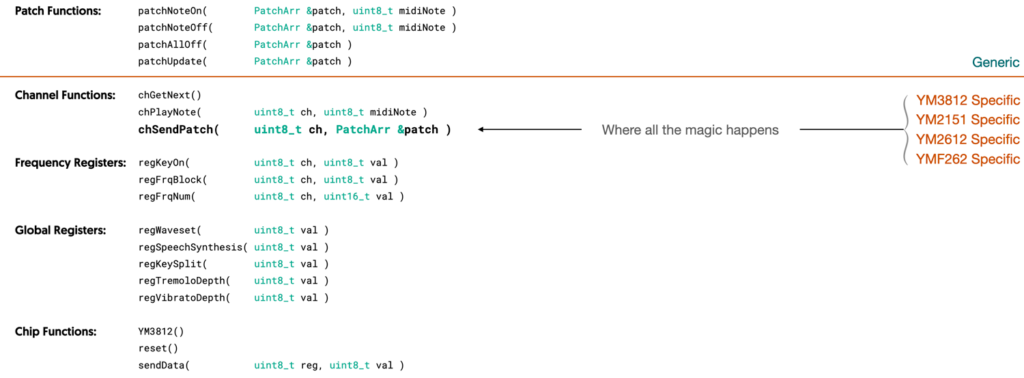
If you draw an imaginary line under the new patch functions, you can see which functions require an understanding of how the YM3812 works and the ones that are fully generic. With this new structure, we can not only turn a note on and off, but adjust the sound settings as well. We only need to know the structure of a generic patch, and we are good to go.
It’s also worth noting that, of the functions below the line, most of the details on how the sound chip works are confined to the chSendPatch function. By altering this function, we can quickly rebuild the library for any number of sound processors.
Creating Instruments
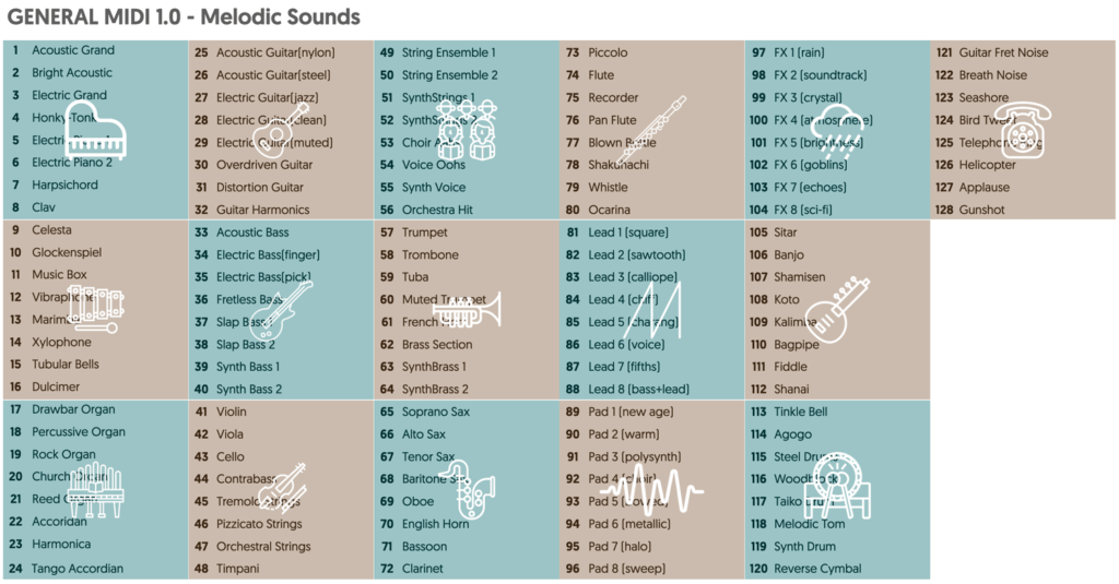
We sure have talked a lot about patches. Patch structures… Patch algorithms… Generic patches… but um… how do we make the patches themselves? Well, this turns out to be a pretty well solved problem. The YM3812 has been around for a long time, and as such there are various patch libraries available. Many of these libraries even follow the General MIDI standard. General MIDI provides a naming convention for patches while leaving the nature of the sound up to manufacturers. The naming convention defines 128 different instrument names broken into groups of eight:
Editing Sounds Patches
For my purposes, I found a library containing the old DOOM sound patches, but if you are interested in editing them or creating your own, I highly recommend the OPL3 Bank Editor project:
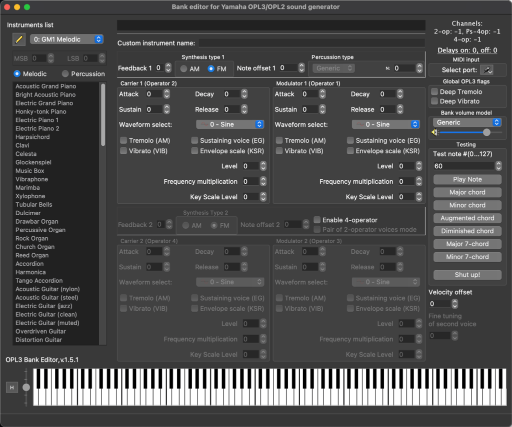
This open source project lets you create and preview 2-operator, 4-operator and even dual 2-operator sounds. You can build up a library of these patches and then export them into a variety of formats.
Instruments.h
In order to use these sounds properties in our module, we need to import all of the information. I took the easy way by creating an instruments.h file that compiles directly into the code. To create this file, start by exporting a patch library from the OPL3 Bank Editor into a DMX .op2 format file. Then you can use a NodeJS program I wrote to generate the instruments.h file. You can find this converter utility in the InstrumentConvert folder on the GitHub for this article. To use it, just put your GENMIDI.op2 file in the same directory and type:
node op2.js GENMIDI.op2 instruments.h
This will create an instruments.h file that you can copy into your Arduino folder. If you peek into this file, you will find a ton of code. But, it really boils down to a couple of things:
- patches[] – Contains all 128 instrument (and 47 drum) patch definitions in our generic patch format
- patchNames[] – Contains character arrays for the names of every patch
- NUM_MELODIC – Defines the number melodic patches (128)
- NUM_DRUMS – Defines the number of drum patches (47)
PROGMEM
If you look closely at the instruments.h file, you will notice the PROGMEM keyword used in the definition of each patch array and every patch label. Here is an excerpt:
const unsigned char ym_patch_0[78] PROGMEM = {0x22,0x00,0x00,0x00,0x00,0x00,0x60,0x00,0x00,0x00,0x40,0x34,0x40,0x40,0x40,0x70,0x08,0x28,0x00,0x18,0x00,0x00,0x10,0x00,0x00,0x00,0x00,0x20,0x02,0x00,0x40,0x40,0x78,0x08,0x78,0x00,0x20,0x00,0x00,0x08,0x00,0x00,0x00,0x00,0x40,0x48,0x00,0x40,0x40,0x78,0x00,0x78,0x00,0x18,0x00,0x00,0x10,0x00,0x00,0x00,0x00,0x00,0x14,0x00,0x40,0x40,0x78,0x08,0x78,0x00,0x20,0x00,0x00,0x08,0x00,0x00,0x00,0x00}; // Acoustic Grand Piano
const unsigned char ym_patch_1[78] PROGMEM = {0x22,0x00,0x00,0x00,0x00,0x00,0x60,0x00,0x00,0x00,0x40,0x24,0x20,0x40,0x40,0x78,0x00,0x78,0x00,0x18,0x00,0x00,0x08,0x00,0x00,0x00,0x00,0x20,0x00,0x00,0x40,0x40,0x78,0x08,0x78,0x00,0x20,0x00,0x00,0x00,0x00,0x00,0x00,0x00,0x00,0x00,0x00,0x00,0x00,0x00,0x00,0x78,0x00,0x00,0x00,0x00,0x00,0x00,0x00,0x00,0x00,0x00,0x00,0x00,0x00,0x00,0x00,0x00,0x78,0x00,0x00,0x00,0x00,0x00,0x00,0x00,0x00,0x00}; // Bright Acoustic Piano
const unsigned char ym_patch_2[78] PROGMEM = {0x23,0x00,0x00,0x00,0x00,0x00,0x40,0x00,0x00,0x00,0x60,0x34,0x00,0x40,0x40,0x70,0x08,0x58,0x00,0x18,0x00,0x00,0x08,0x00,0x00,0x00,0x00,0x00,0x0E,0x00,0x40,0x40,0x78,0x08,0x78,0x00,0x20,0x00,0x00,0x00,0x00,0x00,0x00,0x00,0x00,0x04,0x00,0x40,0x40,0x78,0x08,0x58,0x00,0x18,0x00,0x00,0x00,0x10,0x00,0x00,0x00,0x40,0x0E,0x00,0x40,0x00,0x78,0x10,0x08,0x00,0x20,0x00,0x00,0x08,0x00,0x00,0x00,0x00}; // Electric Grand Piano
const unsigned char ym_patch_3[78] PROGMEM = {0x23,0x00,0x00,0x00,0x00,0x00,0x60,0x00,0x00,0x00,0x40,0x00,0x40,0x40,0x40,0x78,0x50,0x38,0x00,0x18,0x00,0x00,0x00,0x00,0x00,0x00,0x00,0x20,0x08,0x00,0x40,0x00,0x68,0x08,0x78,0x00,0x20,0x00,0x00,0x10,0x00,0x00,0x00,0x00,0x40,0x00,0x40,0x40,0x40,0x78,0x50,0x38,0x00,0x18,0x00,0x00,0x00,0x50,0x00,0x00,0x00,0x20,0x08,0x00,0x40,0x00,0x68,0x08,0x78,0x00,0x20,0x00,0x00,0x18,0x00,0x00,0x00,0x00}; // Honky-tonk Piano
The AVR microcontrollers (and well, a whole lot of microcontrollers) use a Harvard Architecture that splits memory up between Program Memory and RAM. Code resides in Program Memory, while variables (and things that change) reside in RAM.

Microcontrollers typically have far more Program Memory, so it’s useful to store large data constructs in PROGMEM and only load them into RAM when we need to. Our patches array consumes ~13.5k and the patchNames array consumes another 2k. Keeping this in RAM would consume nearly all of it, so instead I’ve put it in PROGMEM. Just keep this in mind, because we will need to write a function to move things from PROGMEM into RAM.
Using the Library in our .ino file
With our fancy new YM3812 library in hand, it’s time to use it in our main program! Let’s go over what we want this program to do:
- Define and manage instruments for every MIDI channel
- Manage MIDI events and play each note with the correct patch
- Listen for MIDI Program Change events that assign patches to channels
Managing MIDI Instruments
Conceptually, we want assign a different patch to each MIDI channel. Those patches come from the patches array defined in the instruments.h file. So, we need to add a couple of lines of code to track this in our .ino file:
#define  MAX_INSTRUMENTS   16                  // Total MIDI instruments to support (one per midi channel)

uint8_t  inst_patch_index[ MAX_INSTRUMENTS ];  // Contains index of the patch used for each midi instrument / channel
The inst_patch_index array contains the indexes of the active patches in our patches array. The array contains 16 elements, one for each MIDI channel. Additionally, we need a data structure in RAM to store the PROGMEM patch information. I called this, inst_patch_data:
PatchArr inst_patch_data[ MAX_INSTRUMENTS ]; // Contains one patch per instrument
Finally, we need a function that loads PROGMEM patch data from the patches array into this inst_patch_data structure:
void loadPatchFromProgMem( byte instIndex, byte patchIndex ){                    // Load patch data from program memory into inst_patch_data array
  for( byte i=0; i<PATCH_SIZE; i++ ){                                            // Loop through instrument data
    inst_patch_data[instIndex][i] = pgm_read_byte_near( patches[patchIndex]+i ); // Copy each byte into ram_data
  }
}
This function takes an instrument index—a.k.a. the MIDI channel to associate with the patch—and the index of the patch from the patches array.
MIDI Event Handlers
In the articles so far, our program only needed two event handler functions—one for note on and one for note off. We still need these two functions, but now we need to adjust them to send patch information:
void handleNoteOn( byte channel, byte midiNote, byte velocity ){    // Handle MIDI Note On Events
  uint8_t ch = channel - 1;                                         // Convert to 0-indexed from MIDI's 1-indexed channel nonsense
  PROC_YM3812.patchNoteOn( inst_patch_data[ch], midiNote );         // Pass the patch information for the channel and note to the YM3812
}

void handleNoteOff( byte channel, byte midiNote, byte velocity ){   // Handle MIDI Note Off Events
  uint8_t ch = channel - 1;                                         // Convert to 0-indexed from MIDI's 1-indexed channel nonsense
  PROC_YM3812.patchNoteOff( inst_patch_data[ch], midiNote );        // Pass the patch information for the channel and note to the YM3812
}
Because we have all of the patch data contained in the inst_patch_data array, all we need to do is pass the patch data associated with the MIDI channel. Note, MIDI channels run from 1..16, not 0..15. So, we have to subtract one in order for it to be zero-indexed.
Next, to allow the user to swap patches via MIDI commands, we need to introduce a new event handler called, handleProgramChange.
void handleProgramChange( byte channel, byte patchIndex ){
  uint8_t ch = channel-1;                             // Convert to 0-indexed from MIDI's 1-indexed channel nonsense
  inst_patch_index[ch] = patchIndex;                  // Store the patch index
  loadPatchFromProgMem( ch, inst_patch_index[ch] );   // Load the patch from progmem into regular memory
}
This event runs every time a MIDI device indicates that it wants to select a different patch. To do that, we first update the inst_patch_index array entry associated with the MIDI channel to point to the new patch index. Then, we run the loadPatchFromProgMem function, to copy the patch data from the patches array into RAM. From then on, any note played on this MIDI channel, will use this new patch.
The Setup Function
In all of the previous articles, the setup function loaded all of the sound settings individually into the YM3812. Now, we have patches to do that, and don’t need any of that noise. So if you compare our new setup function to the old one, it looks a whole lot shorter:
void setup(void) {
  PROC_YM3812.reset();

  // Initialize Patches
  for( byte i=0; i<MAX_INSTRUMENTS; i++ ){            // Load patch data from channel_patches into the
    inst_patch_index[i] = i;                          // By default, use a different patch for each midi channel
    loadPatchFromProgMem( i, inst_patch_index[i] );   // instruments array (inst_patch_data)
  }

  //MIDI Setup
  MIDI.setHandleNoteOn(  handleNoteOn );              // Setup Note-on Handler function
  MIDI.setHandleNoteOff( handleNoteOff );             // Setup Note-off Handler function
  MIDI.setHandleProgramChange( handleProgramChange ); // Setup Program Change Handler function

  MIDI.begin();                                       // Start listening for incoming MIDI

}
That said, we DO need to load an initial set of default patches for each of the MIDI channels from PROGMEM into RAM. Being lazy, I just used a for loop to load them sequentially, so MIDI channel 1 aligns to patch 0, channel 2 to patch 1, and so on.
Finally, we need to call the setHandleProgramChange function from the MIDI library to connect our handleProgramChange function… and that’s it!
Conclusion?
Well, that was a lot of words. I hope they added at least a little more clarity than confusion. But if not, maybe try looking at the code all together on GitHub.
This was a pretty pivotal moment during the development of this module. I can still remember ruthlessly deleting broad swaths of code hoping for the best. And thankfully, everything kind of clicked into place. By abstracting all of the settings into generic patches, we now have the foundation for multi-sound chip modules. And, by loading patches with every new note, we can even implement percussion mode… which will be our topic of discussion in the next article.
Stay tuned! 😉
