Building a Waveform Generator
When starting out in the DIY synth space, one of the first projects people typically tackle after creating their first oscillator is an analog sequencer—like the “baby-8.” It’s a simple circuit that steps through a sequence of adjustable voltages. And if you use those voltages to control an oscillator you’ll get a little tune that repeats over and over.
But what if we turned the clock speed up? Like… WAY up? And, instead of using the output as a control voltage, what if we used those adjustable voltages to directly form a sound wave? Well, that’s what this experiment is about—creating, controlling and visualizing new waveforms.
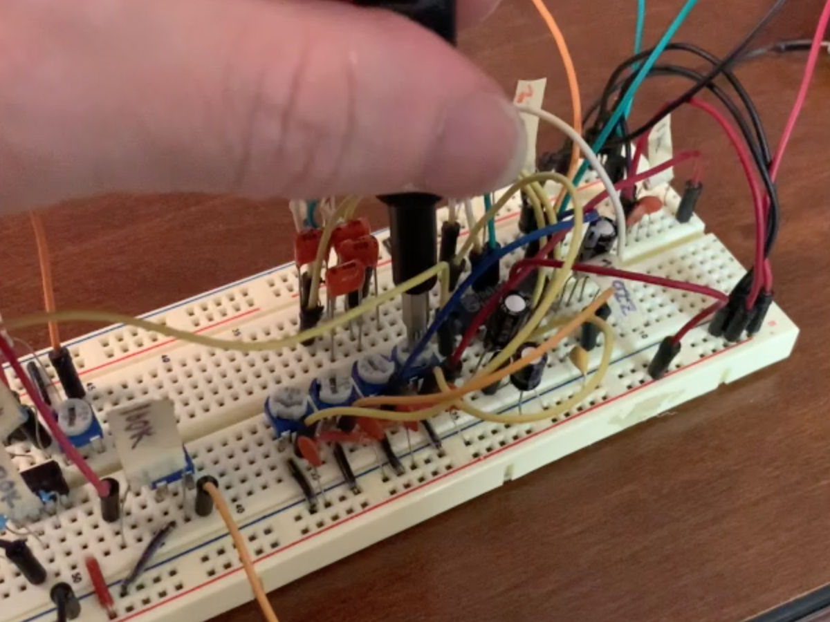
Grab a bread board and follow along—or just read on—either way, let’s dive down the rabbit hole to figure out how this all works.
The CD4017 Decade Counter
At the heart of the Waveform Generator is a CD4017 Decade Counter:
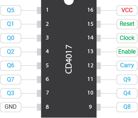
Simply put, this chip turns on one of the Q[0-9] outputs at a time, rotating through them with each tick of the clock input pin. In the “on” state, the Q pin will output VCC which can be anything from 3v to 18v.
There are also a couple of control functions to the chip:
- Reset will flip back to Q0 when it goes high
- Enable turns the chip’s output on and off. I tied this to ground so the chip stays on.
- Carry is an output pin that goes high whenever the CD4017 ticks from Q9 back to Q0. If you were chaining multiple counter chips together, you might use this pin as the next chip’s clock to get a second counting digit. I’m not doing that—but this pin will still be important later…
Creating a Sound Wave
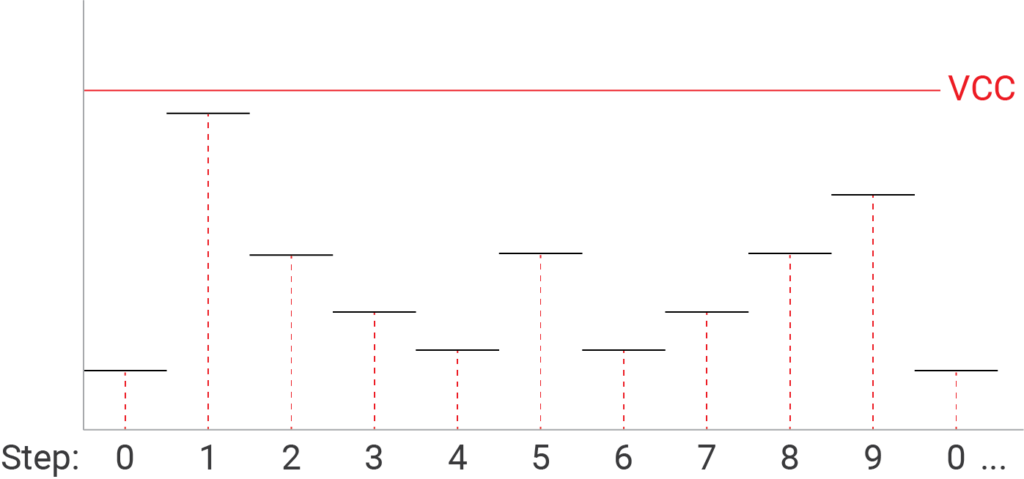
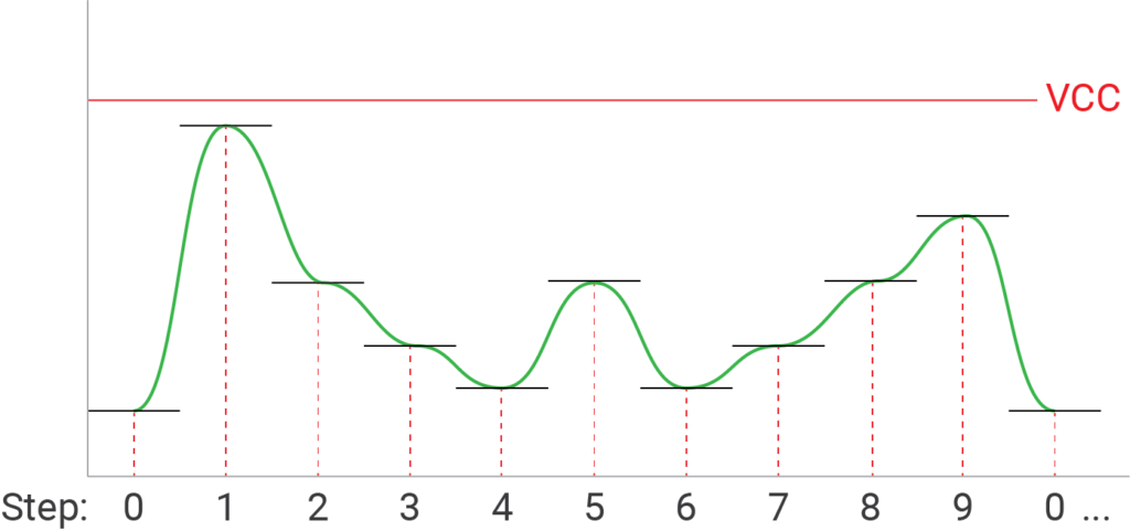
When the clock starts ticking, the CD4017 cycles through pins Q0 through Q9 turning each one on in sequence. And the 5 volts I’m using to power the chip (VCC) gets outputted onto the Q pin that’s turned on.
Now, sound waves are just changes in voltage over time. So if each Q pin generated a different voltage and I combined those outputs together, then as the clock ticks through the different Q pins, I would get a sound wave that looks something like this:
In order to get different voltages for each step in the sequence, I added 10k pots connected from the Q pin to ground. The center pin acts as a voltage divider allowing you to select a value between ground and 5v:
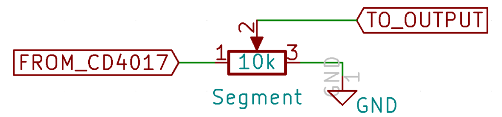
I combined the 10 voltage dividers together through diodes to ensure that none of the signal routes back into the CD4017 chip. Here is the schematic:
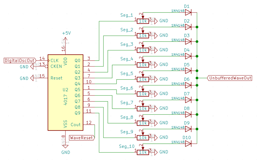
It may look a little complicated, but it’s really just a repeating pattern.
As for the other pins on the CD4017, I tied both the Enable pin (13) and Reset pin (15) to ground. I connected the clock pin to pin D6 on an Arduino Nano, and the Carry-out pin to…
Wait… An Arduino Nano Clock?
Converting a control voltage into a frequency is probably one of the most temperamental parts of any analog synthesizer. Synth designers use some highly temperature-dependent analog circuitry tricks to accommodate the exponential relationship of a 1v/octave control voltage and the Oscillator’s Frequency.
For this circuit, I needed a way to drive the CD4017 clock input using a musically accurate square wave that goes 10x as fast as the desired. The Arduino Nano just so happens to have the ability to generate a very fast, very accurate clock signal using the tone() function. You can set it from 32 Hz all of the way up to 65,535 Hz. Even if you divide that by 10—for each of the 10 steps in the waveform—6,535 Hz is higher than the highest note on the piano (4,186 Hz). Moreover, the Arduino Nano has analog inputs that can read a control voltage and do the exponential conversion in code.
Now I know what you are thinking… isn’t using an Arduino cheating? Won’t it contaminate the purity of all of our analog goodness? Well, the clock signal needs to be a digital signal anyway. And, with the exacting frequency control, temperature stability, the ability to use both CV and MIDI input… it seemed like a good trade-off. Lastly, since the timer is hardware-driven, that leaves most of the processing power on the Arduino for… other things… 🙂
Finnessing the Signal
Let’s take another look at the output of our circuit so far:
Notice how the voltage levels appear to be disconnected line segments? When the CD4017 flips from one Q output to the next, the voltage will instantly change. A waveform like this is going to be really grainy and harsh, with lots of overtones—like a square wave. This might be what you want, but if it isn’t, you’ll need a way to round those corners off so the wave looks a bit more like this:
Rounding waves with filters
To round off the signal, I used a simple low-pass filter:
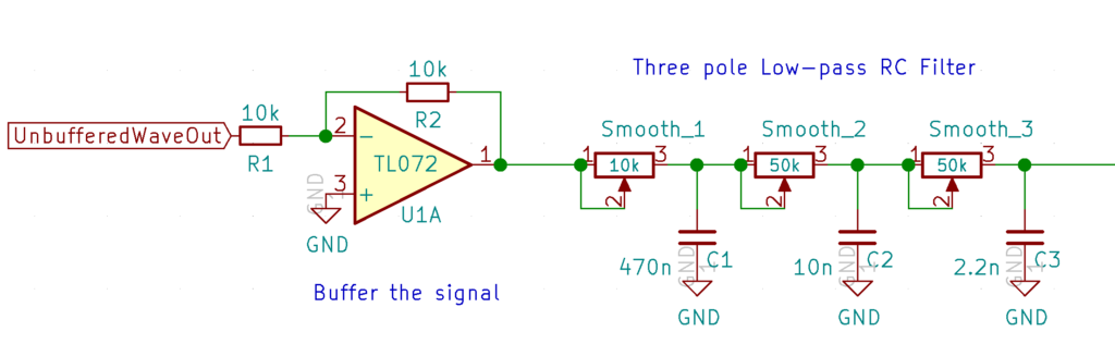
First, I buffered the signal coming from the CD4017 to remove any interaction between the RC Filter and the voltage dividers. This ensured that those square edges remained in the output signal when I turned the filter totally off.
After buffering the signal, I used three low-pass Resistor-Capacitor (RC) filters in series. They each apply a small amount of filtering to round off the output signal without attenuating it too much. Still, they do attenuate it a bit, so after filtering the signal, I added an amplification stage.
Amplifying the signal
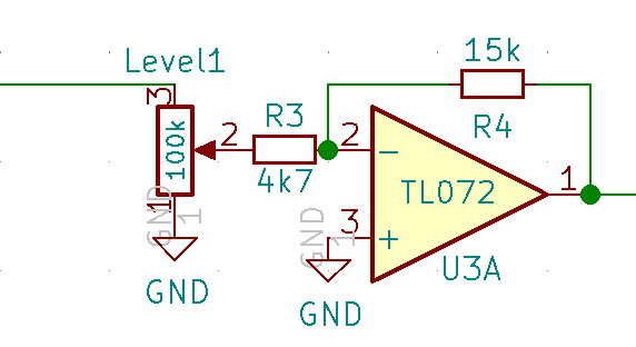
The amplification stage has two parts. A level potentiometer allows you to attenuate the signal coming from the filter between 0% and 100%. That signal is then amplified 3x by the inverting amplifier. This means that the level pot is really amplifying the signal between 0% and 300%.
Note: While this filter & amplification stage will get the job done, it is still pretty primitive and has one significant disadvantage: the filter cutoff doesn’t change as the oscillator’s pitch increases. That’s going to make the sound more hollow as you move up the scale (until you manually adjust the filter accordingly). To fix this, you’d need a much more complicated CV-controlled filter that can adjust the cut-off using a 1v/oct scale. But for now, let’s keep this simple. It works pretty well for an octave or two anyway. Maybe a future article will address this… 🙂
Blocking the DC Offset
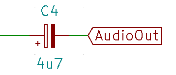
The audio signal is almost ready to use, but I had to do one more thing first. Right now, every segment of the waveform sits between 0v and 5v. This means that the center-line of the wave is effectively 2.5v. Audio waves need to center around ground (0v), and the difference between these center lines is a “DC offset.” You really don’t want a DC offset. Thankfully, it’s pretty easy to get rid of this: just add a large capacitor in series before the output. The capacitor only allows changes in voltage to make it through while blocking any direct current.
A Quick Sound Demo
Now that we know how to generate the sound, let’s take a listen:
Visualizing the Sound
Ok, so we now have a waveform assembled from 10 different segments, filtered with three filters, and then amplified. I’m not sure about you, but visualizing a waveform made from fourteen pots in my head is a pretty steep ask. If only there was a way to visualize this… Wait. Don’t we have a completely underutilized Arduino just waiting for something to do? Why, yes. Yes, we do.
So… an Arduino Nano Oscilloscope?
This seems like a super cheap hack, but honestly… it works surprisingly well. After all, I only need a visual reference and not a precision piece of bench equipment. Here’s a peek at the output (with a few test indicators on top of it):
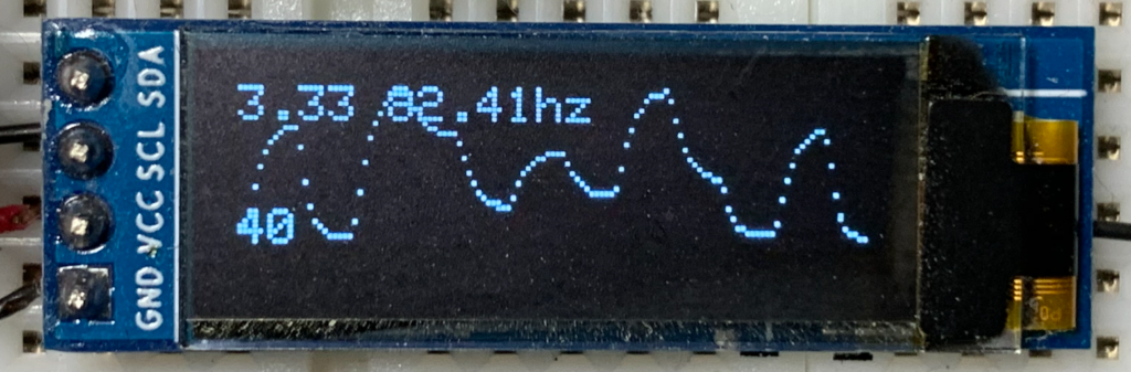
To build this, I basically took the output signal (before it goes into that DC blocking capacitor) and fed it into an analog input on the Arduino. The Arduino captures the waveform and displays it on an OLED screen. There are of course a couple of catches…
Making the signal Arduino-safe
The Arduino’s analog pins can only handle between 0v and 5v. If you go over that, you can easily destroy the analog pins—if not the entire Arduino. And, thanks to that 3x amplifier, the signal can definitely breach that threshold. So I needed a way of clipping the signal:
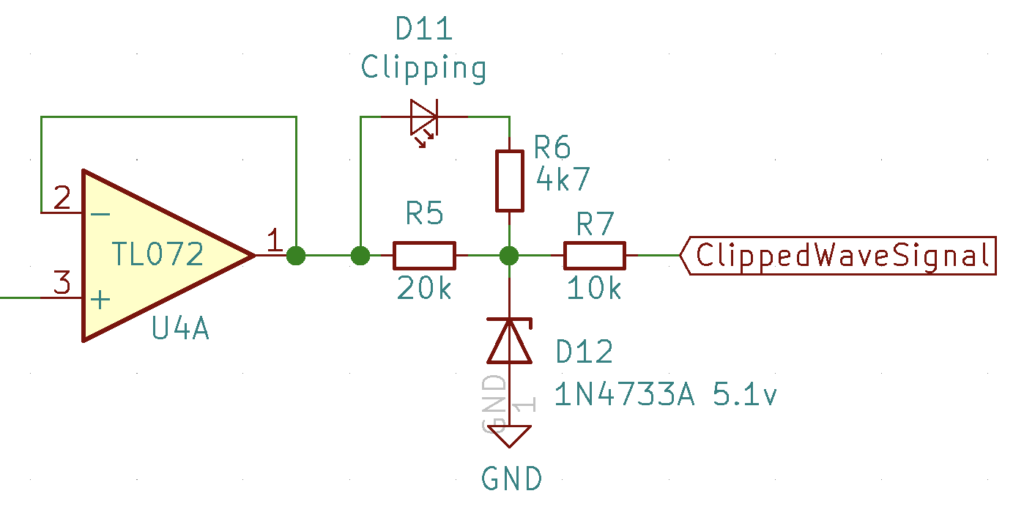
Let’s break this clipping circuit into a few parts:
- The Op-amp (in voltage following mode) just buffers the incoming signal—it doesn’t change it at all. This ensures that the clipping part of the circuit doesn’t interact with the sound output.
- The Zener diode (D12) only conducts when the incoming signal goes above 5.1v or below 0v. This ensures that the point between R5 and R7 stays within the 0v to 5.1v range. And, since R7 is connected to that point, it will never exceed those voltage boundaries either, making it safe to go into the Arduino. R7 also limits the current going into the Arduino—which would otherwise fry it.
- The left side of R5 connects directly to the incoming signal, and the right side connects to the clipped signal. Whenever the signal is within the clipping bounds, the voltage on both sides will be the same. BUT if the signal voltage exceeds the clipping boundaries, then there will be a potential difference across R5. I used that to power a clipping indicator LED (D11) through a current limiting resistor (R6) when the signal exceeds 5v.
Adding CV Input
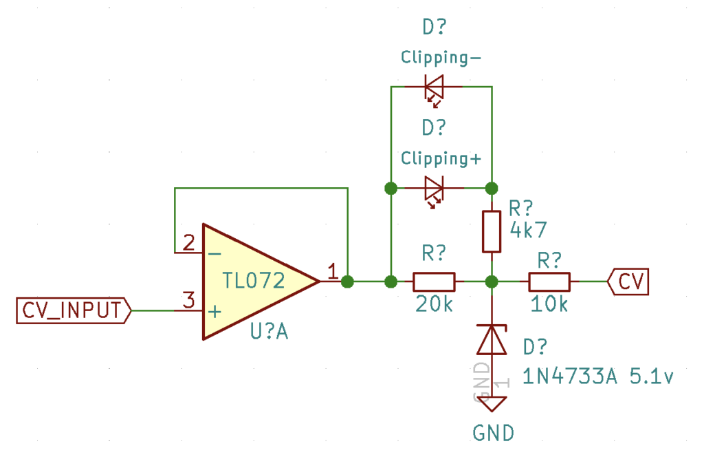
In order to add a frequency control CV input, I used the same clipping circuit, but added a second diode in reverse to indicate negative voltage clipping. On the first circuit, this wasn’t necessary since the voltage could never go negative. But here, in the wilds of modular, anything is possible.
Hooking up the Arduino
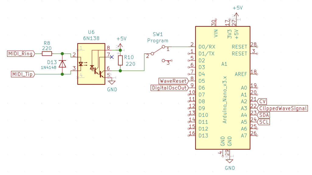
Now let’s take a look at how to hook up the Arduino Nano:
- The clock output that goes into the CD4017 connects to pin D6. Though this could be any digital pin.
- The clipped waveform signal that we want to read into our “oscilloscope” connects to pin A3.
- The CV input signal connects to pin A2.
- The 128×32 pixel OLED screen—which uses an I2C bus—connects to A4 (SDA) and A5 (SCL). These pins are fixed on the Arduino Nano.
- Remember when I said the Carry pin on the CD4017 would be important? Well, that connects to D5 and triggers the Arduino to refresh the Oscilloscope reading right at the beginning of a waveform.
- Lastly, I added MIDI input through an optocoupler (6n138). A switch selects between programming the Arduino and using MIDI input because they both use the RX pin. I typically use 1/8″ stereo jacks for my MIDI connectors (vs. DIN) because they are smaller and cheaper. I follow the Korg pinout because that’s the adapter I happen to have.
Full Schematic
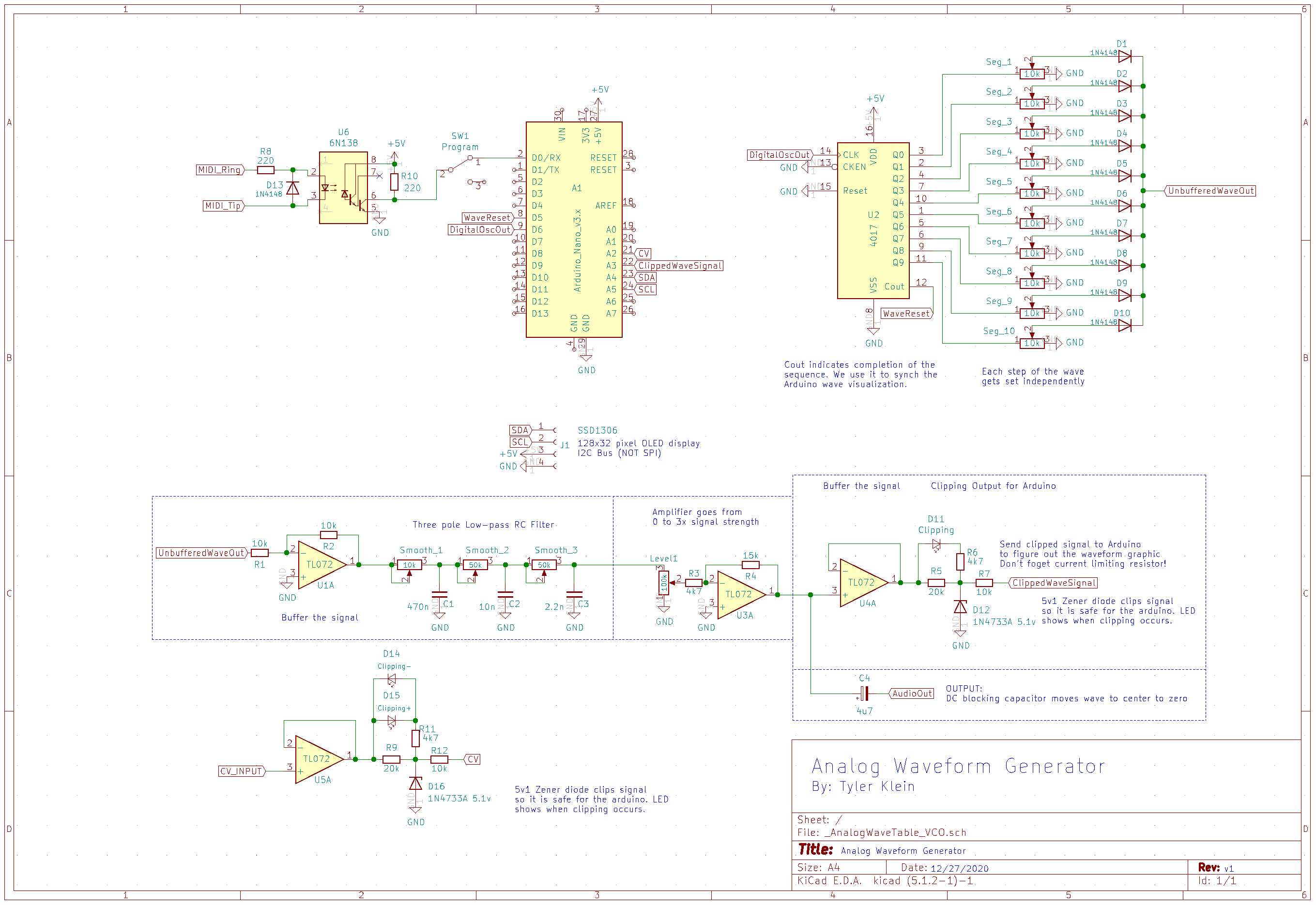
That’s really all there is to the hardware piece of this project. Here is the full schematic. Let’s move onto the software
On to the Software!
One thing I love about the Arduino platform is that there are tons of libraries out there that do all of the heavy lifting. In this case, Adafruit’s GFX library allows us to write to the screen, and the MIDI library manages incoming MIDI messages.
With the hard stuff out of the way, my code primarily focuses on two key things:
- Combining the input CV and current MIDI note into a clock frequency.
- Reading the incoming audio signal, and writing it to the display.
Frequency Lookup Tables
The most difficult part of this programming exercise was figuring out how to combine the current MIDI note with the control voltage input.
In my first attempt, I translated MIDI notes into their corresponding frequencies using a lookup table. This is easy and works great—until you try to combine it with the control voltage input. You can’t just convert a 1v/oct CV into a frequency and add it to the frequency of the current midi note. Let’s say we had a MIDI note of 440hz, and our CV input was 1v. A 1v CV would increase the MIDI note by one octave (adding 440 Hz). But, with a MIDI note of 880 Hz, that same 1v CV would have to add 880 Hz to raise the MIDI note by an octave. Unfortunately, the look-up table was a non-starter.
Calculating the Frequency
In order to abandon the lookup table, I needed a formula that calculates the clock frequency based on the input CV and the current MIDI note. Here is how I got there…
We know that the frequency doubles with every octave increase—e.g. the note an octave above A 440 Hz is A 880 Hz. In this way, you could think of the Frequency Control Voltage (which is 1v/oct) as being the number of times we want to double the current pitch (Base Frequency). Mathematically, you could write this as:
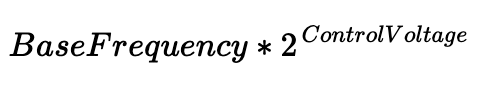
(Where “Base Frequency” is the frequency of the lowest note.)
In the MIDI standard, note 0 starts at 8.1758 Hz and goes through note 127 (12,543 Hz). So we can use 8.1758 as our base frequency. Since there are 12 MIDI notes (half steps) in each Octave, you can convert the current MIDI note into a “1 unit per octave” equivalent by dividing the note number by 12.
Now, since both the CV and MIDI note are on the same linear scale, we can add it to the Control Voltage in the formula above, and this gives us our new formula:
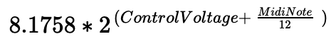
And that’s it. If use the input CV (scaled to 0v-5v) as “ControlVoltage”, and the current midi note as “MidiNote” then the result will be the combined equivalent frequency. Lastly, because there are 10 steps in our waveform, we have to multiply our base note by 10. I used 81.758.
Ok, that’s enough maths.
Coding the Oscilloscope
In order to keep the oscilloscope as responsive as possible, I render the screen in three steps.
Collect Readings
The first step collects 128 readings from the analog input into an array. Keeping the data collection loop extremely simple ensures that readings are collected as fast as possible—providing most granularity.
Draw Screen
Before drawing any pixels, I clear out the display. Then, for each column of pixels, I translate the analog value collected in the array (which ranges from 0 – 1024) to a row on the screen (which ranges from 0 – 32). Lastly, I write a white pixel to the corresponding row and column.
Add any debug info
After rendering the wave, I found it super helpful to add a few other interesting indicators. For example, the currently selected MIDI note, the Input CV value, and of course, the current frequency being played. You can pretty easily turn these on or off to suit your needs. Last thing, don’t forget to run display.display(). This function moves everything from the hidden screen buffer we’ve been writing to onto the actual display.
One more timing consideration
Rendering the screen takes a relatively long time. And, while the clock frequency driving the wave is hardware-driven—and thus unaffected by the screen rendering—changes to the clock frequency ARE affected. This means that if you change the CV input, the corresponding frequency change won’t happen until the screen finishes rendering. This creates audible stuttering in the sound as you change the CV—almost like it is being quantized.
In order to fix this, I only render the screen once every 100 milliseconds, and if the CV Input changes more than a small amount, I wait another 100 milliseconds before updating the screen again.
The trade-off is that if you update the CV continuously the screen won’t update, but the frequency changes will be buttery smooth. As soon as the CV stops changing—even for a split second—the screen will refresh.
Enough talk…
Here’s the code
#include <Adafruit_GFX.h>
#include <Adafruit_SSD1306.h>
#include <MIDI.h>

/**********************
 * Screen Definitions *
 **********************/

#define SCREEN_WIDTH 128 //OLED display width, in pixels
#define SCREEN_HEIGHT 32 //OLED display height, in pixels
//My screen doesn't have a reset pin... so I just picked a random one
#define OLED_RESET     4 //Reset pin (or -1 if sharing Arduino reset pin)
Adafruit_SSD1306 display(SCREEN_WIDTH, SCREEN_HEIGHT, &Wire, OLED_RESET);


/****************************
 * Oscilloscope Definitions *
 ***************************/

#define WAVE_START_PIN  5 //CD4017 carry pin goes high at start of wave
#define TONE_PIN        6 //Output clock pin that drives the tone
#define CV_PIN         A2 //Analog CV input pin
#define OSC_IN_PIN     A3 //Analog input pin for oscilloscope measurement

#define REFRESH_DELAY 100 //Milliseconds between OLED screen refreshes

//This is where we will track the values for oscilloscope measurement
//We will collect one value for every column of the display
int vals[SCREEN_WIDTH];

unsigned long next_refresh = 0; //Tracks time between screen refreshes


/********************
 * MIDI Definitions *
 ********************/

MIDI_CREATE_DEFAULT_INSTANCE();
byte current_note = 23; //Contains the currently played midi note.
                        //Defaults to 23 so the CV input of 0v will start
                        //at C (32.7 hz) even if MIDI input is not used.

float last_CV = 0.0;   //Sotres last CV value. This is used to determnine
                       //change in CV over time (for OLED refresh)

//MIDI note on handler:
void handleNoteOn(byte channel, byte note, byte velocity){
 current_note = note;
}

//MIDI note off handler: (nothing to do here really)
void handleNoteOff(byte channel, byte note, byte velocity){
}


/******************
 * SETUP FUNCTION *
 ******************/

void setup() {
  pinMode(WAVE_START_PIN, INPUT); //Set Wave Start pin as an input

  // SSD1306 Display Setup
  if(!display.begin(SSD1306_SWITCHCAPVCC, 0x3C)){ //Addr. 0x3C for 128x32
    for(;;);                                      //Fault. Stop here...
  }
  display.setTextSize(1);              //Set Text Size to be really small
  display.setTextColor(SSD1306_WHITE); //Make Text white
  next_refresh = millis();             //Set next refresh time to be ASAP

  //MIDI Setup
  MIDI.setHandleNoteOn(handleNoteOn);   //Add event handlers for Note On
  MIDI.setHandleNoteOff(handleNoteOff); //Add event handlers for Note Off
  MIDI.begin();                         //Initiate Midi

  tone(6, 880); //Set a tone to start with
}


/*****************
 * LOOP FUNCTION *
 *****************/

void loop() {

  //--- SET THE TONE CLOCK FREQUENCY ---//

  //Step 1: Read CV pin and convert it to between 0 and 5
  //Analogread returns a value [0 to 1024], we need a value [0 to 5]
  //You can simply multiply the reading by (5 / 1024) = 0.0048828125

  float current_CV = float(analogRead(CV_PIN)) * 0.0048828125;


  //Step 2: Convert MIDI note to an equivalent CV and add to current_CV
  //Because there are 12 notes per octave, and one volt represents one
  //octave, all we need to do is divide the current MIDI note by 12.

  current_CV += float(current_note)/12;


  //Step 3: Convert Control Voltage into a frequency
  //We will assume that the zero'th MIDI note is 8.1758hz which is "C"
  //Because there are 10 steps per waveform, we multiply this by 10

  float freq = 81.758 * pow(2,current_CV);  //BaseFreq x 2 ^ CV
  tone( TONE_PIN, freq );        //Tone function sets CD4017 clock pin


  //--- UPDATE THE SCREEN ---//

  //Step 4: Determine whether it is safe to update the OLED screen
  //When fast CV changes occur, it sounds like the tone quantizes.
  //This is because the Arduino can't update the tone value while it
  //is updating the OLED screen. By checking CV delta, we can see how
  //much it changed and then skip the screen refresh to keep things
  //buttery smooth.

  if( abs(current_CV - last_CV) > .015 )
    next_refresh = millis()+REFRESH_DELAY;

  last_CV = current_CV; //save the current CV for the next loop


  //Step 5: See if it is time to refresh the screen:

  if( (millis() > next_refresh) ){


    //Step 6: Wait for the start of a new wave by repeatedly
    //checking the WAVE_START_PIN pin

    while( digitalRead(WAVE_START_PIN) == LOW ){}
    next_refresh = millis() + REFRESH_DELAY;   //update refresh timer


    //Step 7: Collect analog values for each column of the display
    //We want the timing to be as fast and consistent as possible,
    //hence we just read and store the values

    for( byte i=0; i<SCREEN_WIDTH; i++ ){
      vals[i] = analogRead(OSC_IN_PIN);
    }


    //Step 8: Clear the OLED screen and plot each pixel on the screen
    //Since the screen is only 32 pixels tall, we have to map the analog
    //input value that goes 0-1024 to 0-32. Because both 32 and 1024 are
    //powers of 2, we can right-shift the analog input by 5 bits leaving
    //only the most significant 5 bits left over. Those remaining 5 bits
    //go from 0-32. This method is extremely fast, but if you have a
    //different screen height, you will need to adjust this function.

    display.clearDisplay();
    for( byte i=0; i<SCREEN_WIDTH; i++ ){
      display.drawPixel(i, vals[i]>>5, SSD1306_WHITE);
    }


    //Step 9: OPTIONAL - Display some values on the screen

    display.setCursor(0, 25);      //Current MIDI note in the bottom left
    display.print(current_note);

    display.setCursor(0, 0);       //Combined CV in the top left
    display.print(current_CV);

    display.print(" ");            //Clock freq after the CV value
    display.print(float(freq)/10);
    display.print("hz");


    //Step 10: Update the display
    //Since all changes were made to a hidden display buffer, we have to
    //tell the screen update the display based on the buffered changes
    display.display();

  }

  MIDI.read(); //Update MIDI to see if any signals came through
} By
By 

3 thoughts on “Waveform Generator”
Peter Hesterman
Hi, Tyler,
I thought I’d try out the waveform generator while I’m waiting for the next installment in your YM3812 series. I’m having some trouble getting this to work, and I’m wondering if it has something to do with my not powering the op-amps correctly…I’m applying 5v at pin 8 and connecting pin 4 to ground…is that correct? If not, how are you powering all of the TL072s? I’ve been reading up on op-amps, but I have to admit my knowledge there is pretty shaky. Also, if I don’t have a 20k resistor for R5 in the clipping circuit, I can just substitute 2 10k resistors in series, right?
Thanks,
Peter
Tyler in reply to Peter Hesterman
Hey Peter! I think you are correct. The issue is probably how you are powering the op amps. I ended up using +12v on pin 8 and -12v on pin 4. (Realizing now that I left this out of the schematic—-woops!) If you don’t have a bipolar power supply, it might be possible to rework things using just +5v, but then you will need to connect the + input of the op-amps to a “virtual ground” of 2.5v. Also, you’d probably need a different op-amp that supports voltages closer to the VCC/VDD rails like a OPA2604. Probably the easiest thing to do would be to just use +/- 12v on the OpAmps if you can. As for the 20k resistor, 2x10ks in series would definitely give you 20k. But honestly, I’m not sure how critical the exact value is. You can always try a 10k and see if that just works. Best of luck!
Peter Hesterman
Thanks for your reply, Tyler!
What bipolar power supply do you use for the +/-12v? Would a DC +/- buck-boost converter do the job?
Would a 22k resistor be a suitable replacement for the 20k?
Did you use your BeatStep to generate the control voltages in the video?
Peter