Introduction
I’ve been meaning to build a noise generator for a while now—especially to make hi-hats, claps, and other percussive sounds. So when my noise2 chip arrived from electricdruid.com, I was eager to dig in. As I looked through the datasheet schematic, I was really surprised by the simplicity of the module design.
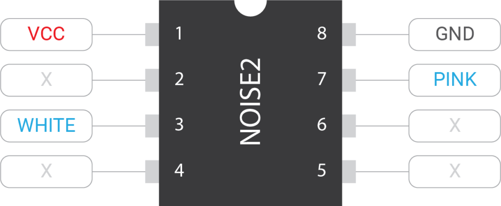
The chip has outputs for pink and white noise, so short of powering things, you just need to route the pink and white noise outputs through voltage followers for protection, maybe add a low pass filter on the white noise output, and that’s basically it!
Have you ever wondered about the difference between pink and white noise? All noise is made up of a combination of sine waves of different frequencies. Those waves are added together to create sounds of different timbres. White noise contains sine waves of every frequency all at equal volume. Now, because the frequency of a pitch increases exponentially for every octave, there are more frequencies in higher octaves than in lower ones. For this reason, white noise—to our human ears—sounds high pitched. Pink noise however, equalizes the volume of the frequencies so that each octave has the same total volume.
Adding a Filter
Seeing as there wasn’t much to the noise circuit, I decided to integrate the noise2 chip into the VC Tone Filter experiment that was occupying my breadboard at the time. This experiment uses a TDA1524 tone chip (designed for Treble / Bass / Volume adjustments in cheap stereos), to create something like a VCF/VCA combo.
After adding the noise chip, I experimented to see what kinds of sounds it could generate. I added an envelope generator on loop and, with a little fiddling, got everything from ocean waves to howling winds, to hi-hats, cymbals, claps, footsteps, and base drums. Here is a sample of some of the sounds. It’s about 5 minutes of tweaking settings—feel free to skip around.
It was clear to me that this thing needed the full module treatment.
Module Design
After a bit of consideration, I came up with a list of features to include. Most of these are pretty standard for any module:
- Output buffering / protection
- CV inputs that you can attenuate
- Selectable voltages mixed with CV inputs (so you can override)
- Adjustable Resonance / Feedback
- Selectable pink noise / white noise / no noise
- A buffered input signal (which really just allows you to use the module as a combo VCA/VCF instead of the noise)
- Eurorack power connector
The Filter
The filter circuit stayed largely the same as the version in my previous experiment. I used the TDA1524 as the core of the filter, and because the chip supports two channels (left and right) I fed the output of the right channel into the input of the left channel. This doubled the effect of the filters.
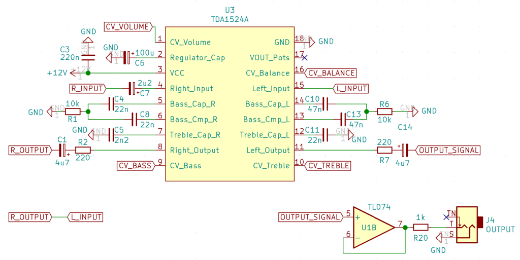
While the components are largely the same, I did tweak a couple of values—lowering the capacitance of C4 and C8, and raising the capacitance of C10 and C13. Because the same signal flows through both the left and right channels, the balance control acts as a choke. When balance is turned all the way left, the signal gets amplified before being attenuated on the right side (and visa versa). The signal is only loudest when it is centered. So, by having different capacitors on the left and right side, you get an imbalance between the channels, and this gives you very different sounds as you adjust the balance control.
Inputs & Feedback Loop
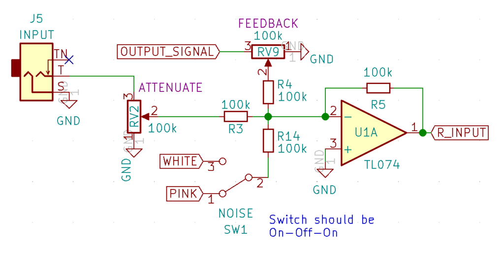
The feedback loop mixes together the input signal, the white/pink noise, and the filter’s output using an inverting buffer (with unity gain) to create the filter’s input signal. The feedback potentiometer adjusts the attenuation of the output signal to determine the amount of resonance. Note, for the noise switch, you will want to use one of those three-position “on-off-on” switches so you can turn off the noise.
CV Input Mixers
All of the CV inputs (except balance) follow a standard active mixing design:
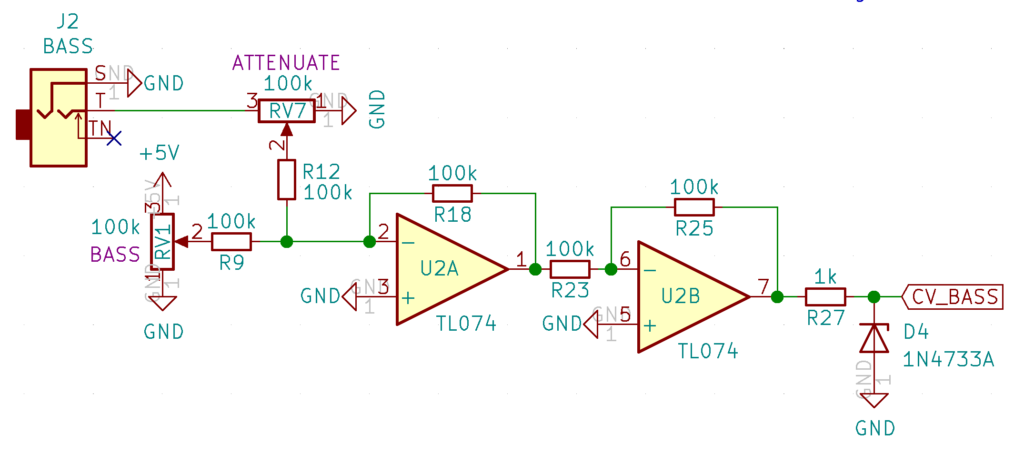
The CV input attenuates through a potentiometer before being mixed together with a voltage divider. The two inverting amplifiers (unity gain) ensure that the signals mix without cross-talk and the Zener diode (D4) ensures that the CV gets clipped before it can damage the TDA1524 chip.
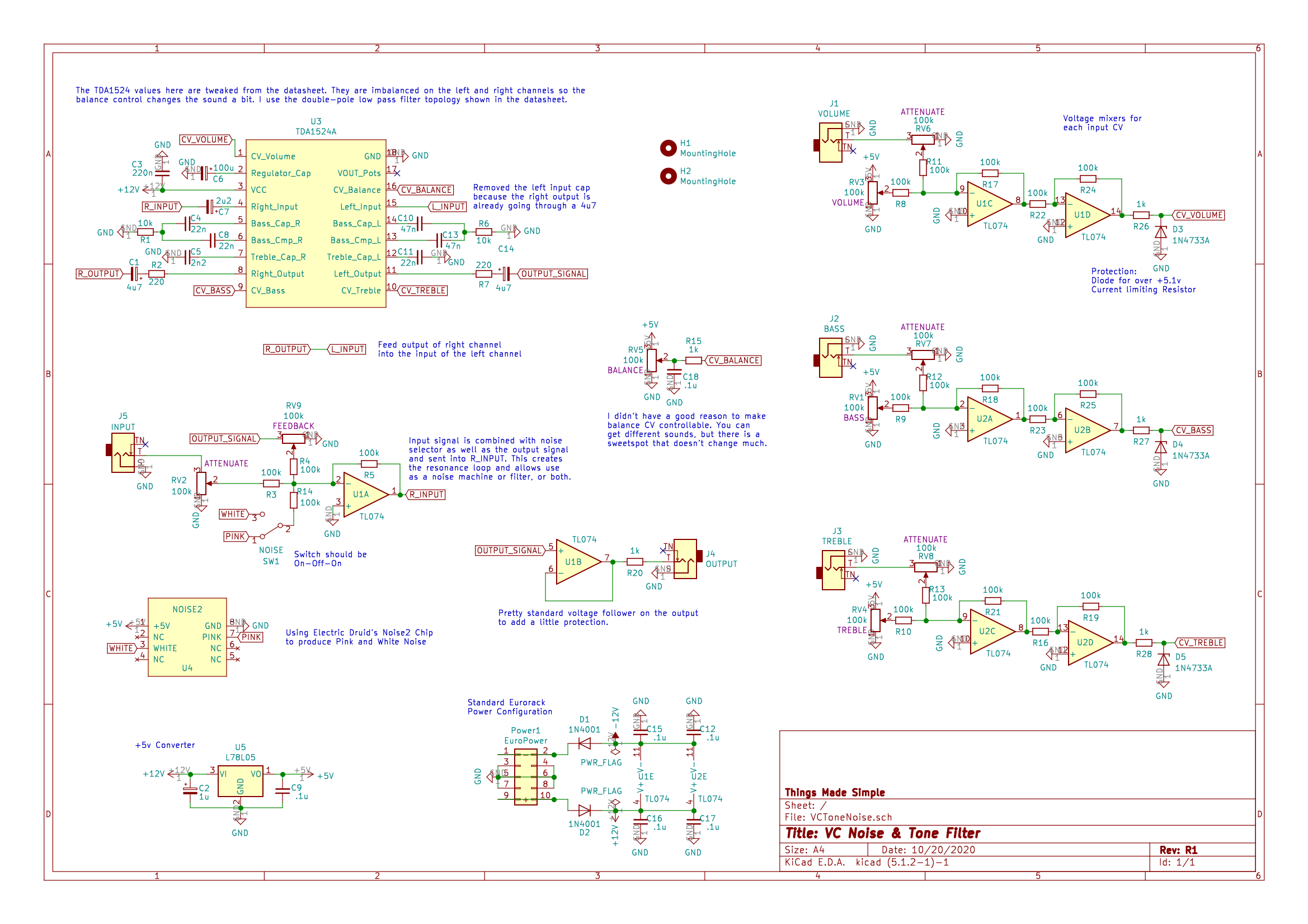
Full Schematic
Here is the full schematic that also includes the power filtering components. Nothing super crazy there, although as a best practice, I do include low voltage-drop rectifier diodes on the power input to prevent frying the module by plugging it in backwards.
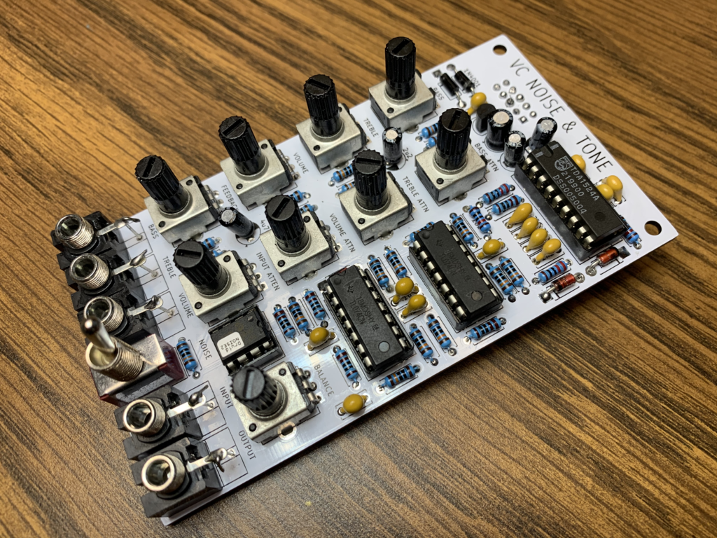
PCB Layout
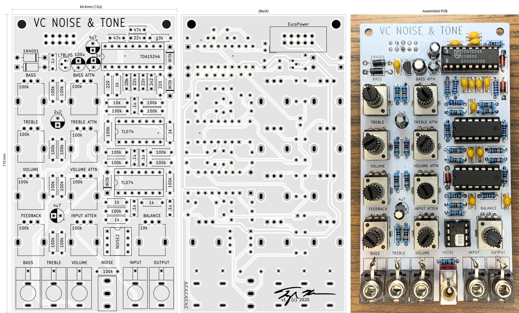
After a bunch of fiddling in Kicad, I came up with a rather densely packed single-board PCB layout. The 12u width (60.6mm) feels quite usable and not too cramped. Of course, if creating the most tightly packed Eurorack device is your thing, I bet you could make it smaller by stacking two boards. Personally, I only try to do that when the savings is closer to 40% or so. Here, given the number of physical controls, and the fact you do want SOME space between them, I think you’d probably only save maybe 20% on the board width. Also, hey this is a White/Pink Noise Generator, VCF, and VCA all in one, so 12 units seemed like a pretty good value to me. 🙂
One more note, I added M3 holes at the top of the module for front-panel stand-offs because the pots I’m using are super cheap ones without panel mounts. Without better pots, you need something at the top to fasten on the front panel. Also, keep an eye on those caps sitting between the potentiometers. If they get too tall, they might run into the front-panel. This isn’t too big of a deal because there is plenty of room to bend them down against the board if you have to.
Module Demo Time
The module is extremely versatile and can be used to create lots of effects. To demonstrate as much as possible, I broke the video into two parts. The first part uses the module purely to alter an input signal with the noise turned off. In essence, it acts as a filter—even resonating at one point. In the second video, I turned the noise source on and showed how it can be shaped by the filter and even mixed with the input signal.
As always, if you have any ideas on how to push this module further, please leave a comment! The device is a blast to play with and I will keep trying to improve it. Maybe starting with a proper faceplate.
~Cheers!~
 By
By 


10 thoughts on “Noise & VC Tone Filter Module”
Steve
Thanks for putting up your schematic, it answers a lot of questions I had looking through the datasheet. I like the idea of having different filter cap values on the left and right channels and using the balance control to mix them, I’m definitely stealing that!
Tyler in reply to Steve
Awesome! Let me know how it turns out. The balance is interesting, it acts like a choke. In the middle, both sides let sound pass, but if you go left or right, it amplified and attenuates or attenuates and amplifies the signal. The capacitor imbalance allows more of the signal to get through and it’s an interesting distortion effect. Good luck with the build!
Steve
?
One thing I picked up from the datasheet is that pin 17 should be connected to the upper value of the control voltage range if you’re not using the internal potentiometer supply (tables at the bottom of page 5/top of page 6 of the September 1987 Phillips datasheet in case there’s multiple versions around). It’s not made particularly explicit in the text (it’s not the greatest datasheet, but at least it exists). I’m unsure how much of a difference it would make to the sound but it might be worth considering…?
Tyler in reply to Steve
Oh, Interesting! I didn’t notice that. It might be worth shorting it to see what happens. I just assumed it was supposed to sit there unused. The other option would be to connect it to the input potentiometers instead of +5v. Then you could swap the noise chip out for a transistor-based noise circuit and get rid of the 5v regulator altogether. If you end up trying it out, let me know! ?
jc2046
Hi Tyler,
I have some ideas to expand in this circuit and I would love to get a pair of PCBs to experiment with. If you could sell it, or share the gerbers, or interchange for another parts that would be great
Im the founder of Spherical Sound Society and I have all this in stock to pretty much interchange (at tindie or etsy)
I adore this site to bits. Cheers!!
Tyler in reply to jc2046
Hey JC,
Thank you for your interest and the kind words! Definitely willing to exchange modules. I pinged you on FaceBook messenger.
Thom
Hi Tyler, Are you selling the panels for this module design? I am interested in building one to try out and learn more about how the circuits work. Please get in touch. Thanks.
Tyler in reply to Thom
Hey Thom, Thanks for your interest! I sent you an email reply.
Jos
Question: why do you use 5.1V zener diodes? If I’m not mistaken the datasheet of the TDA speaks of a max of 4.25V at the control inputs?
Tyler in reply to Jos
That’s a great catch, I think you are correct, that zener should probably be a 1n4730 or maybe a 1n4731. So far I haven’t had any issues with the signal being too hot, but I suppose it could damage the chip in the long run.