Introduction
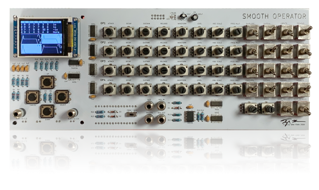
Watching LMNC build the Sega Mega Drive Synthesizer inspired me to build an FM Synth of my own. I loved how all of the controls were broken out and that you could adjust the sound on the fly. I wanted to replicate that in a Eurorack-sized module, and this is how the Smooth Operator came to be.
The Smooth Operator is simply a controller for a sound module daughterboard. It breaks out all of the sound settings into 34 potentiometers and 18 switches—no menu-diving required!
For the sound processing daughterboard, I used the OPL-3 module from the MidiBox Hardware Platform. This module houses a YMF262 sound processor, YAC512 DACs, and all of the related analog circuitry. While the YMF262 is slightly different from the YMF2612 used in the Sega Mega Drive, they are both 4-operator FM Synth chips and sound very similar.
The OPL-3 module has a compact design that provides low-noise, high-quality sound output. And, because the project is open-source, the schematics and PCB layouts are freely available. You can even buy a printed board from modular addict.
Smooth Operator Features
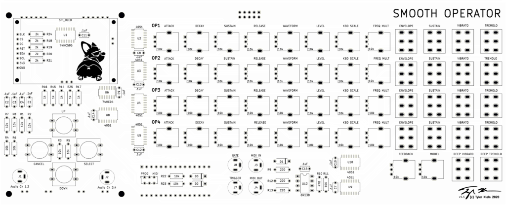
- A 128×160 pixel TFT display provides a readout of all settings and a visualization of the four operator envelopes.
- All four output channels output through two stereo jacks.
- Midi In/Out allows you to connect your keyboard or Midi controller
- Gate/Trigger outputs allow you to connect other Eurorack modules for external audio processing.
- An Arduino Nano provides the brains of the operation controlling everything while keeping the device easy to program.
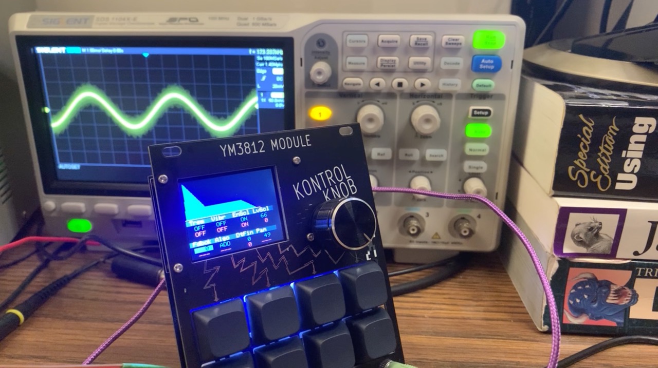
Before taking on this project, I first built a similar device using Yamaha’s YM3812 OPL-2 sound processor, and I highly recommend this inexpensive kit from Cheerful Electronic as a way to get started. Having only two operators to control simplifies the physical interface and programming. And, since the OPL-3 is backward-compatible with OPL-2, you can leverage most of your OPL-2 code in the OPL-3 device. In fact, I drew heavily from DhrBaksteen’s OPL-2 code library to write my OPL-3 Arduino library.
YMF262 Sound Chip Features
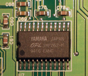
This FM synth chip powered many of the sound cards from the early 1990s including the SoundBlaster 16, Pro AudioSpectrum, and probably 20 others. It defined the new OPL-3 standard that replaced OPL-2— which powered the original Adlib and Sound Blaster music cards.
- Operators form the basic building blocks of FM Synthesis. Each operator includes an oscillator, ADSR envelope, amplifier, and low-frequency oscillator (for vibrato/tremolo effects). The OPL-3 chip includes 36 operators and allows you to configure them in a variety of ways.
- You can mix the sound from each operator directly or use one operator to modulate the frequency of another. And when a high-frequency oscillator modulates the frequency of another high-frequency oscillator, magical things start to happen. This chip allows you to combine up to 4 operators through different algorithms to form a “voice.” In 4-Op mode, you can play 6 simultaneous voices, and in 2-Op-mode you can have up to 18!
- In the 4-Op, 6 voice mode as well as the 2-Op, 15 voice mode, you also get five rhythm sounds to build some sweet drum tracks.
- The oscillators of the YMF262 support 8 different waveforms including a square wave, sine wave, and a bunch of other variants. These provide tons of flexibility in creating different sound timbres.
- You can also mix the voices together into any of the four output channels. This provides some rudimentary surround sound functionality, but I could imagine repurposing it for a Eurorack integration that independently processes pieces of sounds and recombines them later. Sky’s the limit!
Hardware Overview
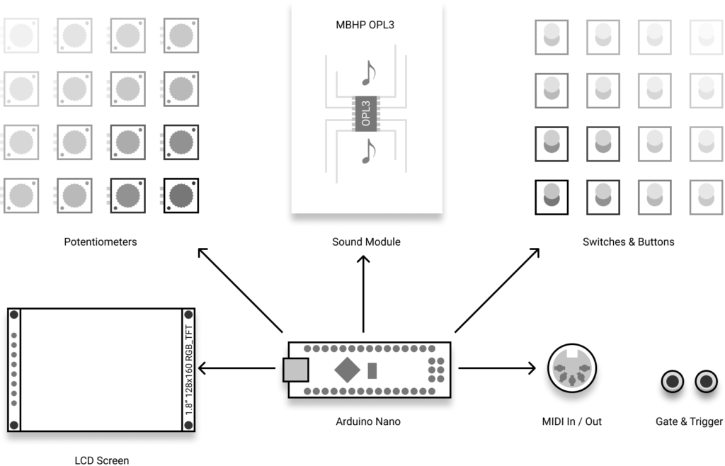
Smooth Operator hardware breaks down into 5 key sections—all controlled by an Arduino Nano. We will go through each in detail:
- A grid of potentiometers & Switches and buttons that allows you to adjust the settings for each of the operators and control the menus
- Controller interface for the MBHP OPL-3 sound module
- A TFT display for visual feedback of the settings
- A Midi In/Out Interface circuit
- A circuit to output Gate and Trigger signals
Demo Time
Helpful Links
Before we go deeper, here are a few links that I found extremely helpful in my journey:
- YMF262 Datasheet – This provides tons of information about the chip, how to communicate with it, and how to set everything up. Print this out, and keep it close. You will need it!
- YAC512 Datasheet – This provides the information you need to build out the Digital to Analog Converter circuitry that connects to the YMF262. If you use the OPL-3 module kit above, you probably won’t need to refer to this much.
- OPL3 Programming Guide – Wow was this site helpful. It goes way beyond the datasheet, and provides detailed explanations of all the YMF262 registers.
- A beginner’s guide to FM Synthesis – This primer on FM synthesis explains how operators, carriers, and modulators work together to create sound.
Pots & Switches
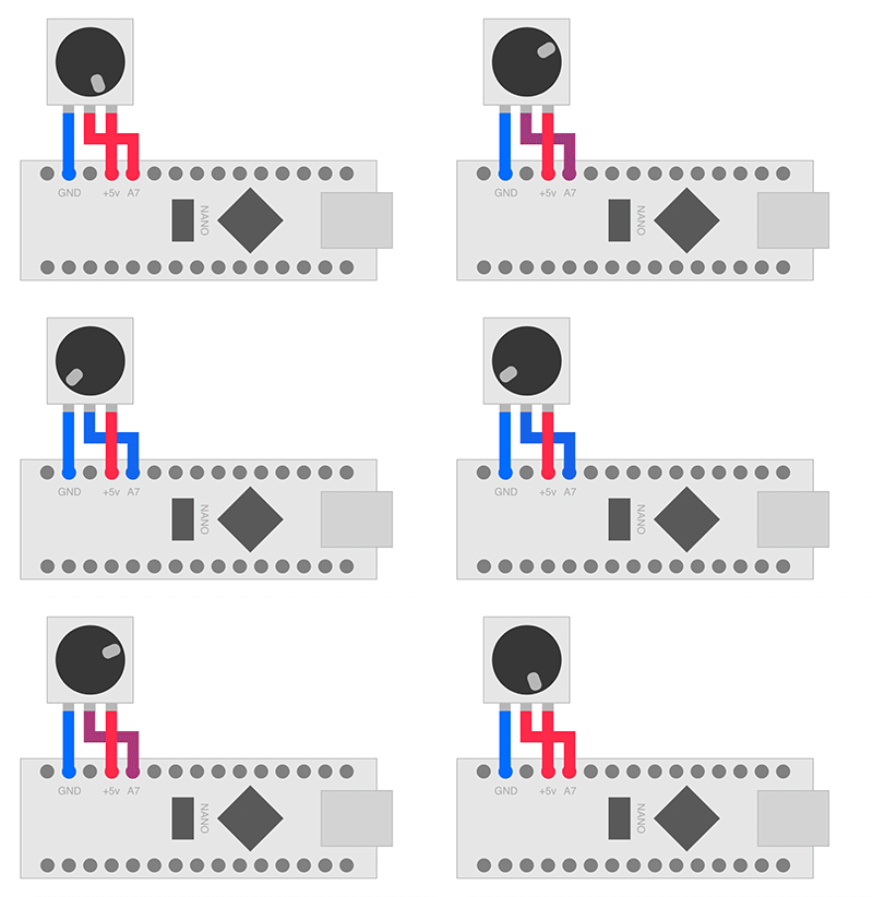
As it turns out, the Arduino makes it pretty easy to wire up and read a potentiometer. You just put a wire from one side of the pot to ground and the other side to +5v and then the middle wire directly into an analog input. The potentiometer acts as a “voltage divider” and depending on how far you turn the dial, outputs a voltage between 0v and 5v. The Arduino reads this voltage and uses its digital-to-analog converter to turn it into a number between 0 and 1,024. Easy breezy.
Similarly, a switch alternates between two different connection states: ground (0v) or 5v. The Arduino turns this into 0 or 1,024 (all off or all on). Incidentally, this type of switch is called a “single pole, double throw.” It has one connector (pole) that can be connected to one of two other connectors (throws). If you look for these switches online, search for “SPDT” or “1P2T.”
Reading Many Analog Inputs
If you look closely at the Arduino Nano, you will see only 8 analog inputs. Our device needs 56! How are we going to read 34 pots, 18 switches and 4 buttons with only 8 analog inputs??
Enter the CD4051 Analog Multiplexer. You can think of this like a switch, but instead of 2 throws it has 8, and instead of using your finger to flip it, we use a binary value. Here is a block diagram of the chip:
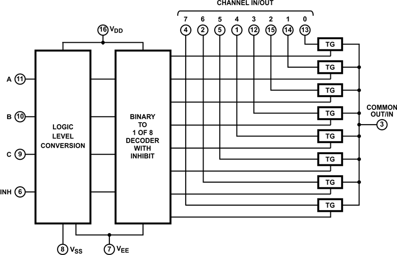
- At the top are all of the “Channel In/Out” pins. Each of these connects to the middle pin of a different potentiometer or a switch.
- On the right is the “Common Out/In” pin. This pin connects to the Arduino.
- The CD4051 allows you to select which of the channels at the top connects to the common pin on the right. And it does this using the A/B/C pins on the left. These three pins use a binary number from 0 (all pins off) to 7 (all pins on) to select one of the channel lines.
- What about that INH pin? Well this handy little guy disconnects all of the channels from the common pin. Why would you want to do that? Well, right now we only have 8 channel inputs, and we need 56. That means we need a bunch of these chips as well as a way to turn them on and off.
A Giant 56-input Multiplexer
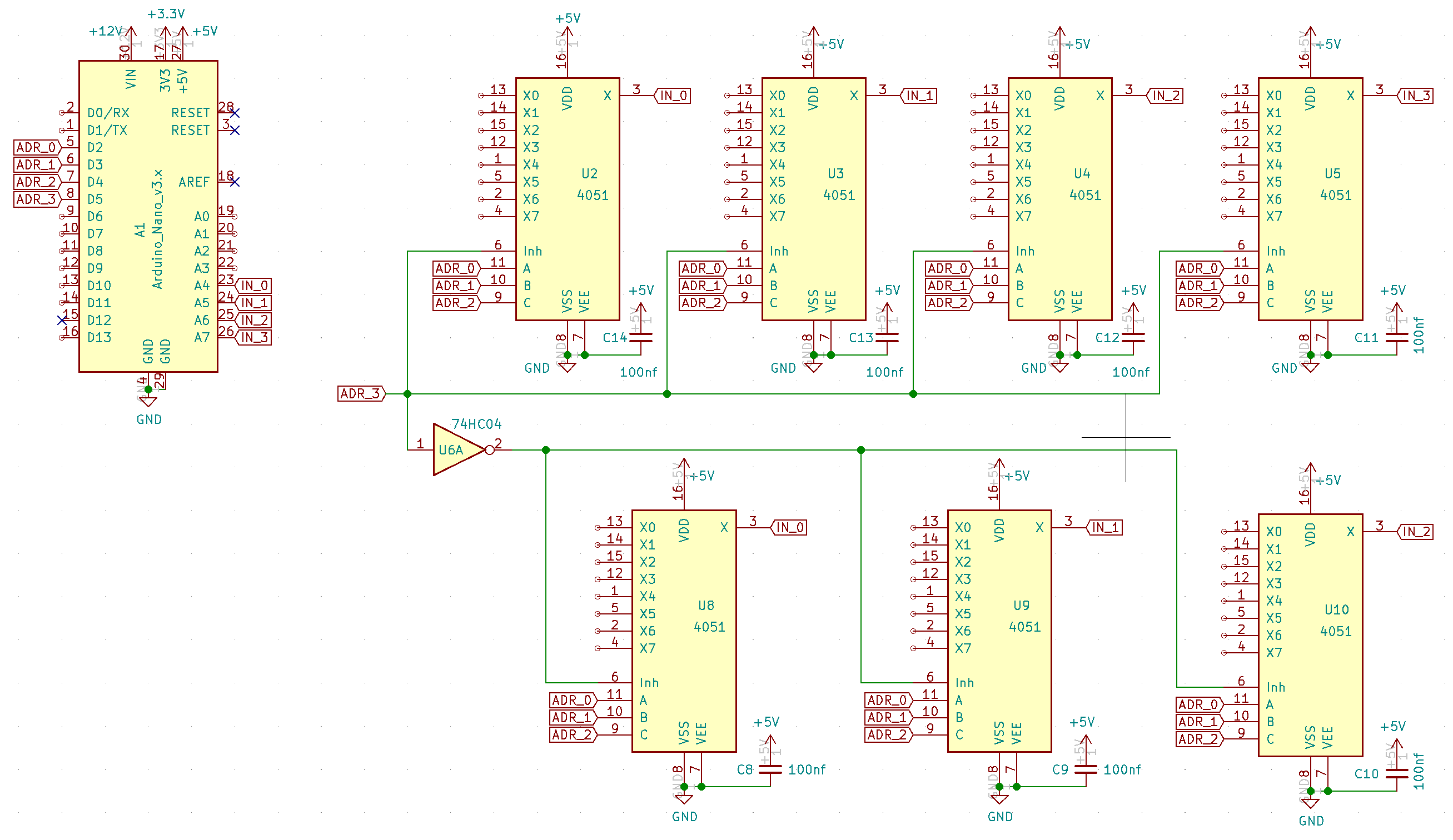
The above schematic shows just the connections between the Arduino and the 4051 multiplexers. Notice that the first three address lines are all connected together across all 7 of the 4051s. The fourth address line connects directly to the INH pin of the top four chips, but then inverts before connecting to INH on the bottom three chips using a 74HC14 hex inverter chip.
The output of each of the four 4051s on top goes to one of four analog inputs on the Arduino. And, because the top and bottom rows will never be connected at the same time, the bottom row feeds into the same analog input pins.
When we get to the software side of things, you will see that putting a 4-bit binary address on the Arduino’s D2-D5 pins results in being able to read 4 analog values on pins A4-A7.
One thing to note here… In case you were thinking about choosing pins A0-A3 on the Arduino, it turns out that pins A6 and A7 can ONLY be used as analog inputs. Since that is exactly what we need in this case, I used pins A4-A7 to ensure the more flexible pins are available for other purposes.
Connecting Pots & Switches
Now, see all of those connectors marked X0-X7 on each of the 4051 chips? Those are the inputs that will connect to our pots and switches.

Connecting the pots is pretty self explanatory. One side ties to ground, the other to +5v and the middle goes to one of the inputs on the 4051. Above is an example showing one Operator’s worth of pots. I used 10k pots because they seem to allow enough current to drive the A/D converter in the Arduino. I have had mixed success with 100k pots.
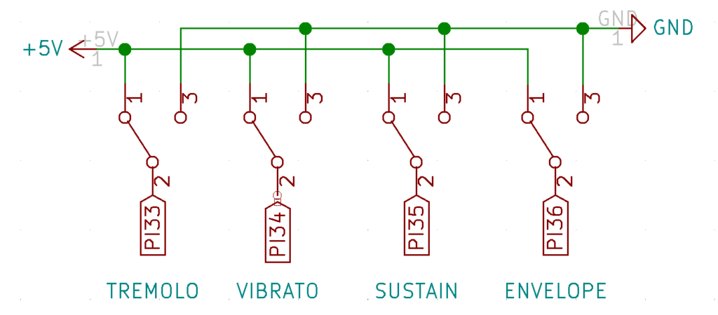
Switches are just as easy as the pots. One side goes to ground, the other to +5v and it works!
Experiment gone wrong (a brief aside)
On my first attempt, I thought it would be great to power the pots and switches with a nice clean +5v power rail to ensure that the Arduino’s A/D readings would be more accurate. So I created a separate +5v power rail and tied all of the pots and switches to it. I still powered the 4051s (and all of the other chips) off of the Arduino’s +5v. Theoretically, that should be awesome. But in practice, the Arduino’s +5v sometimes dropped below the other (less loaded) power rail, and when the pot’s output exceeded the 4051 chip’s power, it got hot and died. After replacing all seven of the surface mounted 4051s, I combined the two +5v rails into one and everything worked great. LESSON: don’t get fancy, just use the Arduino’s 5v rail for everything.
Debouncing Buttons
You’d think buttons would work the same way as switches, but of course, they don’t. In practice they tend to “bounce” between on and off as you press them. This makes navigating menus impossible, because every button press registers as multiple different presses. This sends you frustratingly passed the option you were looking for. But never fear, WE HAVE THE TECHNOLOGY, and we can fix this with a bit of “debounce” circuitry.
The bouncing comes from a brief moment where the button just starts to make contact. During this moment (also known as an eternity to a micro controller operating at millions of cycles per second) the button goes back and forth between making contact and not making contact. We need to filter out that noise during the transition period and only detect the fully-on and fully-off states.
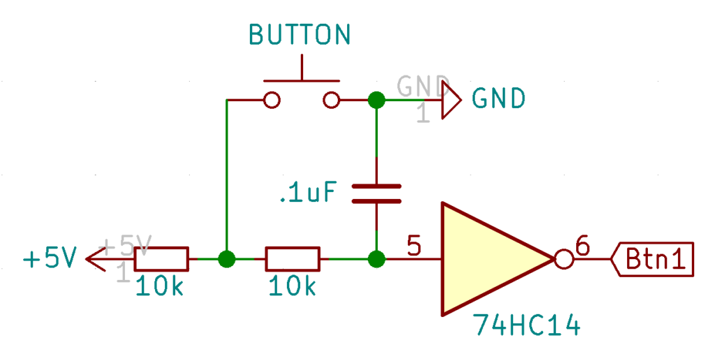
As far as debouncing circuits go, I made this one fairly complex, but also very reliable. If all of this looks like magic, let’s re-draw the circuit and break it down into its individual parts:
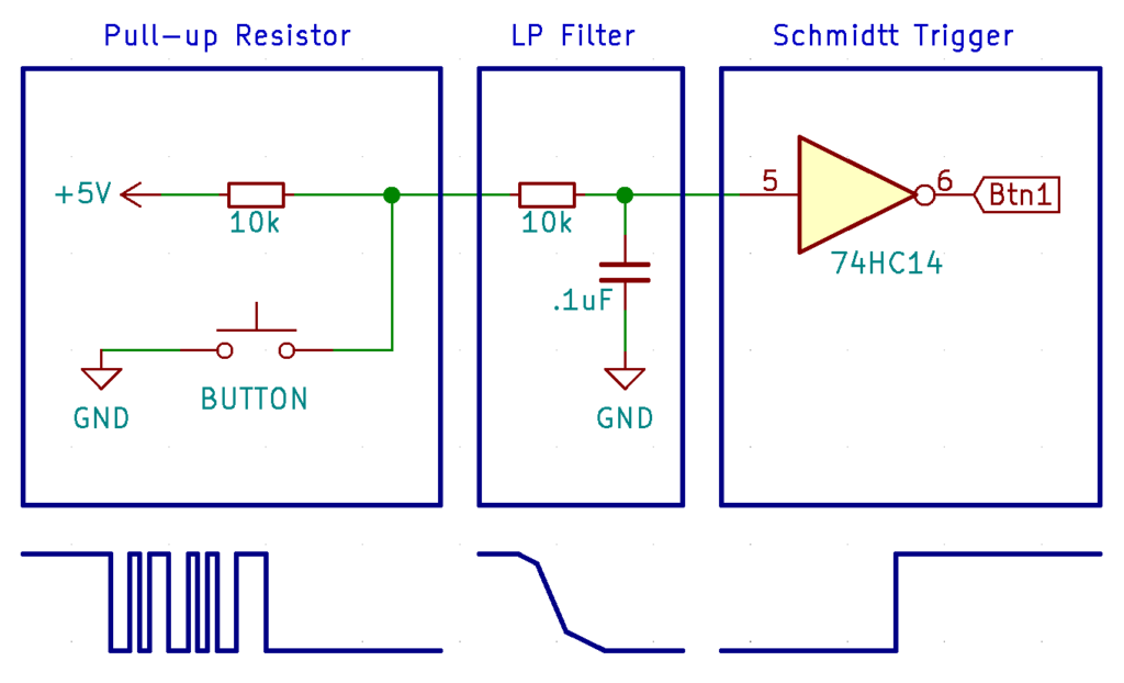
Pull-up Resistor:
The first part of the circuit ensures the button signal is either “on” (5v) or “off” (GND). Before you press the button, the output connects to 5v through a “pull-up” resistor. When you press the button, the output shorts to ground. This ensures a reliable output voltage of either 5v or 0v and no state in which the output “floats”—creating unpredictable voltages.
Even though this first part of the circuit ensures the output is either all on or all off, the output signal will flutter back and forth until it stabilizes in the on or off position. To fix that, we need a way to filter out this high frequency noise. We need a “Low-pass RC Filter.”
Low-pass RC Filter:
An RC Filter contains a resistor and a capacitor—hence “RC.” In our case, we use a 10k resistor and .1uF capacitor. With these values, the filter will smooth out any bouncing noise over 160 hz. The filter will also elongate the transition from high to low. To get a sharp transition, we need one more piece…
Inverting Schmitt Trigger:
The third part of the circuit inverts the output. This way, when you press the button, the output goes high and when released, it goes low. Of course, the 74HC14 isn’t just an inverter, it also contains a Schmitt Trigger. This means that for the input to go from low to high, it has to go above the high threshold (~2.0v) and to go from high to low it has to drop below the low threshold (~1.3v). Having two thresholds instead of one dramatically decreases the effect of any remaining noise and reduces the elongated input from the filter into a nice sharp transition.
The OPL3 Connector
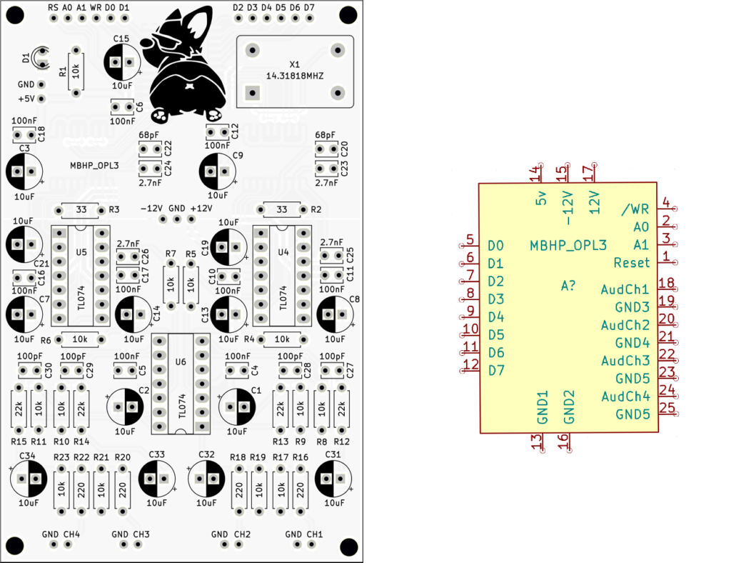
The MidiBox Hardware Platform (MBHP) OPL-3 module sits at the heart of the Smooth Operator. It houses the YMF262, the D/A converters, and all of the analog circuitry needed to produce sound. We can control the device through an 8-bit data bus and a few control pins.
Note: By consolidating the audio hardware like this, we can actually build all kinds of hardware modules that can plug into the Smooth Operator. As long as they have the same form factor and use the same control circuitry they should be compatible.
Without getting into the details of the module itself, let’s instead look at how to connect to it. These connections come in four types:
- Power: +5, +12, -12 and GND power connections
- Audio: 4 audio output channels (both signal & ground)
- Data: 8-bit bus (D0-D7) for sending data
- Control: Signals that tell the module when and where to write the data
Transmitting Data
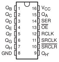
First, we need a way to control the 8 data pins without using up all of the pins on the Arduino Nano. To do that, we make use of the Arduino’s SPI bus. This serial port is very fast and we can convert the serial signal to an 8-bit parallel one using a 74HC595 shift register.
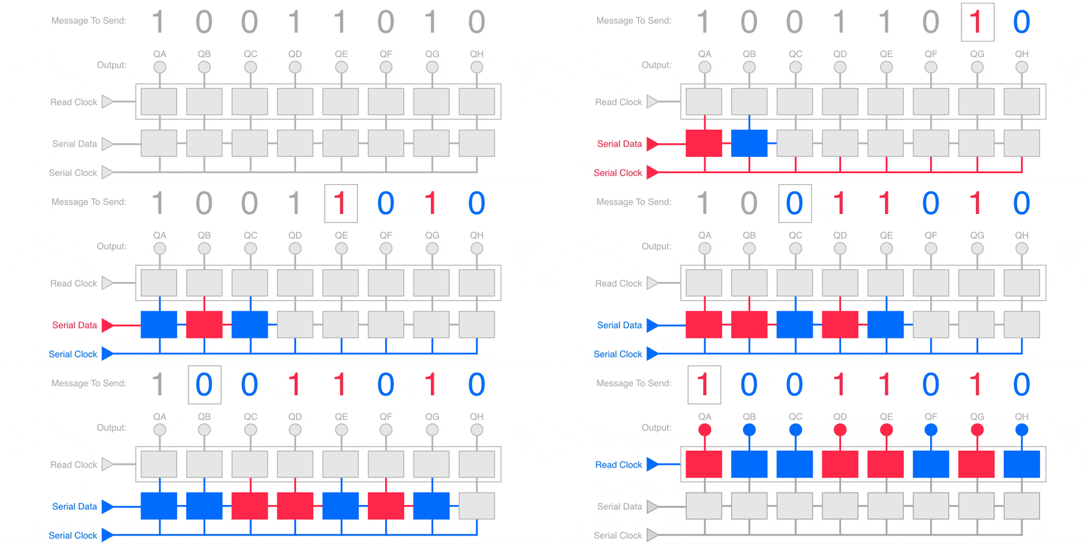
The shift register reads serial data coming into SER (pin 14) using SRCLK (pin 11) for timing. Inside the chip, there are two sets of 8 flip-flops. The first set stores the data as it comes in, shifting over one bit at a time with every pulse on SRCLK. The second set of flip-flops latches the output of the first set as soon as RCLK pulses high.
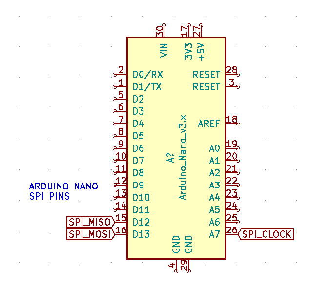
This lines up really nicely with the SPI bus on the Arduino. Connect the MOSI pin (master out) to the SER pin on the 74HC595, and the SCK pin (Serial Clock) to the SRCLK pin. Now the 74HC595 will capture the serial data from the SPI bus. In order to see that data on the output (QA-QH), we also need to latch the data by pulsing the RCLK pin. So, connect RCLK to a data pin on the Arduino—I chose D6, but it doesn’t really matter.
OPL-3 Module Control Pins
What about those control pins? Well, let’s take a closer look:
- /WR: tells the module to write the data on the bus into the YMF262. Note, the “/” means that a transition from positive to ground signals a write.
- A0: tells the module whether we are selecting a register or writing data to the currently selected register.
- A1: tells the module to which register set we are writing. We need this because the YMF262, contains two different register sets. This was an improvement over the OPL-2 standard which only had one set.
- Reset: tells the YMF262 to reset everything.
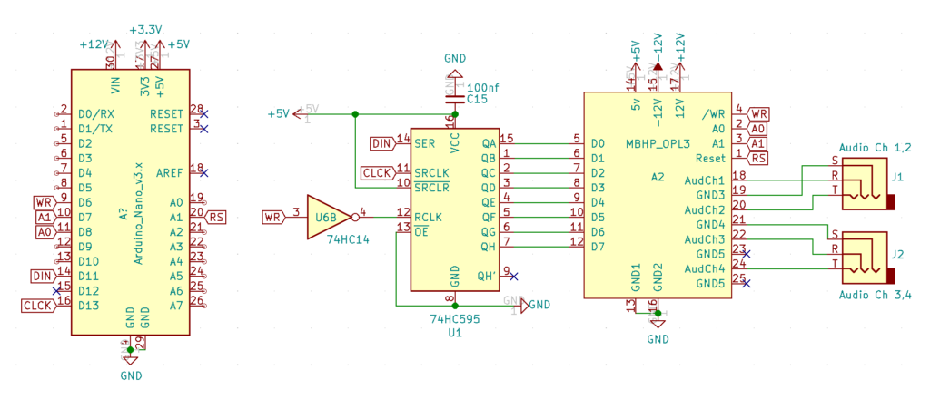
A0, A1 and Reset can all be managed in the software on the Arduino. So you can connect them to any pin that can output a digital signal—I used D7, D8 and A1.
74HC595 Control Pins
As for the other pins on the 74HC595, tie /SRCLR high—we don’t need to clear the serial data. And you can tie /OE (operation enable) to ground—we always want to listen to the incoming serial data. QH’ is used for chaining together multiple 74HC595 shift registers, so we can leave that unattached.
We only trigger the /WR pin after loading data into the 74HC595. And as it turns out, we can use the same signal to latch the data onto the shift register and tell the module to read the data bus. The caveat is that /WR needs a negative pulse instead of a positive one. No problem. If we send the signal through the 74HC14 inverter, we get just what we need.
One final note: The module’s audio channel outputs each come with their own ground connection. While the output jacks sit on the Smooth Operator PCB, these ground connections are NOT connected to the ground plane of the Smooth Operator board. This would create a ground loop and cause all kinds of unwanted noise. You gotta keep ’em separated.
Are you thirsty for more?
The TFT Display
The TFT display is a critical component of the Smooth Operator. It provides visual feedback for all 50 of the patch settings as well as a graphical representation of the four envelopes. The beauty of organizing everything on one screen is that you don’t have to menu-dive to see how things change AND if you want to “save” a patch, you can just take a picture of the screen. 🙂
The Screen Module:
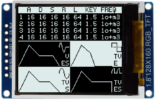
The screen module itself is a 1.8″ 128×160 TFT display that I purchased from AliExpress. There are lots of different types of these screens with different interfaces, so make sure yours has all 8 pins like the image above. Those pins are (GND / VCC / SCL / SDA / RST / DC / CS / BLK). A lot of similar screens don’t expose the Chip Select (CS) pin, but you really need it. The screen shares the SPI bus with the sound module, so we need to tell it when it is time to listen.
In case you were curious, here are the screen dimensions. These came in handy throughout the design process:
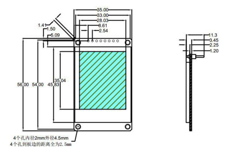
Hooking up the screen:
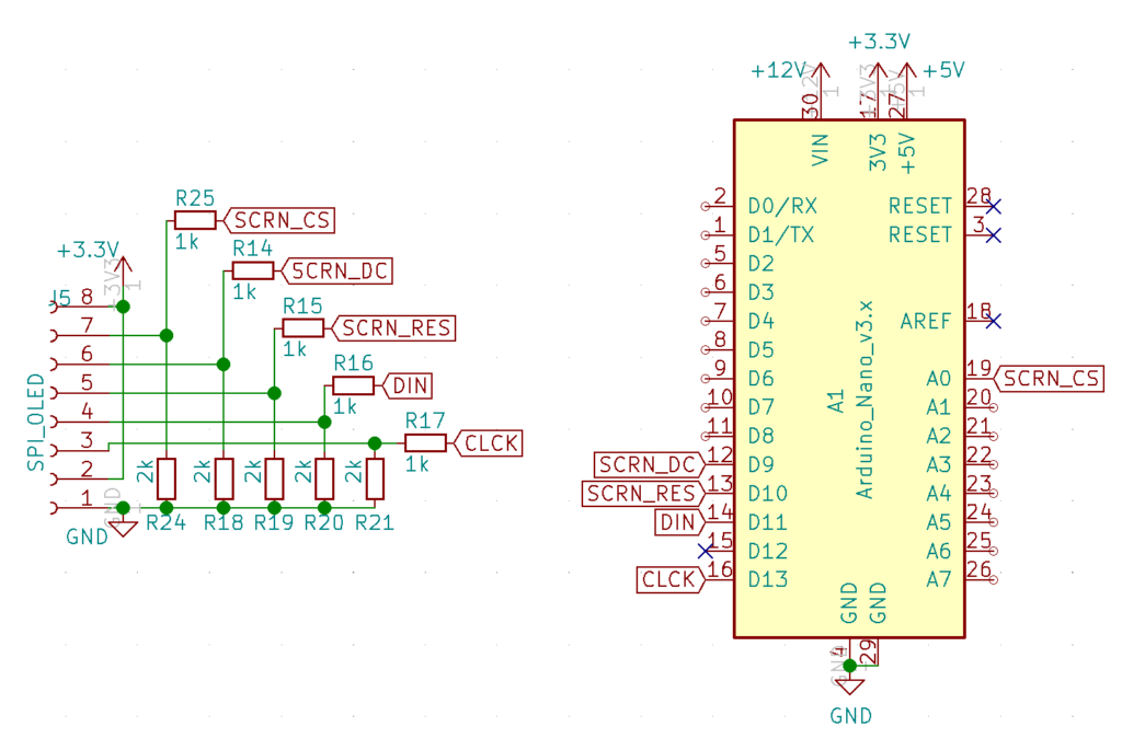
To connect the screen to the Arduino, I used the same SPI bus as the OPL3 module. I also connected the reset, chip select, and DC pins to their own digital pins on the Arduino (D10, A0, D9).
Note that the screen operates at 3.3v instead of 5v. Luckily the Arduino has a 3.3v regulated power output that we can use to power the screen. However, the data pins still operate at 5v and we need to use voltage dividers to lower them to 3.3v.

A voltage divider consists of two resistors in series with one side connected to the signal, and the other side connected to ground. The output signal comes from the point between the two resistors which allows about 2/3 of the 5v signal (or 3.3v) to pass into the screen.
MIDI Communication
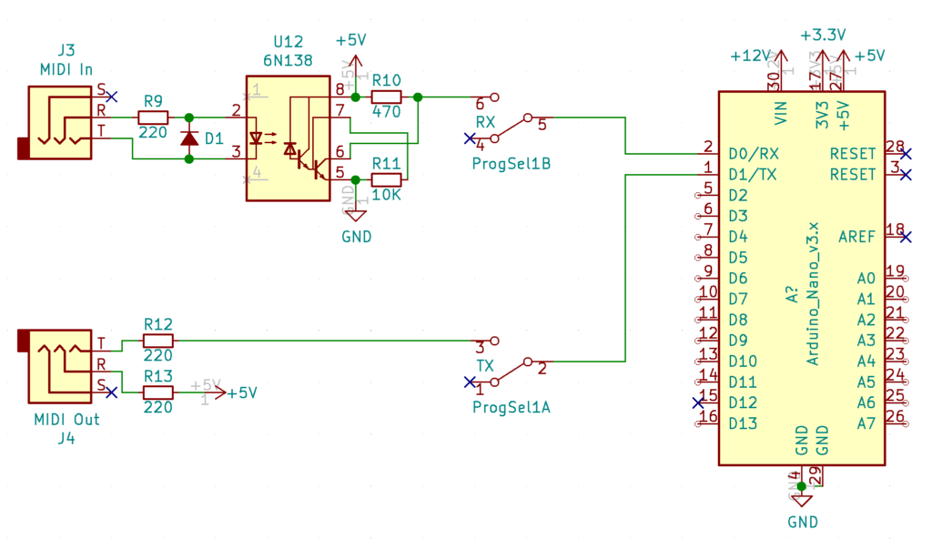
MIDI connections are really just serial connection similar to the RX/TX pins on the Arduino. In fact, the only reason we don’t just directly connect the two together is because we want to ensure any unanticipated incompatible connections don’t harm the larger circuit.
To do this, we isolate incoming messages using an “opto-isolator.” The 6N138, contains a light emitting diode (LED) and photo sensor embedded inside of it. When the light turns on, the photo sensor allows current to flow through the circuit which passes the message on to the Arduino.
Note: because the Arduino Nano uses the TX/RX pins for its USB connection, I included a dual-pole, dual-throw switch to flip between USB mode (for programming the Arduino) and MIDI mode. Since this isn’t something you interact with frequently, I just used one of those micro switches.
A trip down the rabbit hole…
To really understand how the MIDI circuit works, it might make sense to re-draw it so MIDI Out and MIDI In are connected through a cable. Imagine that TX is connected to one Arduino and RX is connected to another Arduino:
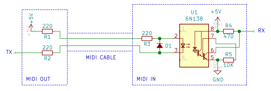
The circuit on the left side of the 6N138 is pretty simple. +5V comes in from the power rail, through (R1), through the MIDI cable and into (R3). It then passes through the LED inside the 6N138, goes back through the MIDI cable, through another resistor (R2) and into the Arduino’s TX pin.
When transmitting data, the Arduino brings the TX pin HIGH shutting off current flow (because both sides of the LED are at 5v) and LOW which turns on the LED, sinking the current into the Arduino’s TX pin. The diode (D1) ensures that if the cable was inverted, current would flow around the 6N138 without damaging it.
On the right side of the circuit, the photo diode receives the signal and amplifies it through the two transistors contained in the 6N138. These transistors switch the signal, so when the LED is on, RX goes low, and visa versa.
In the end, when TX goes Low, so does RX, and visa versa.
Gate & Trigger
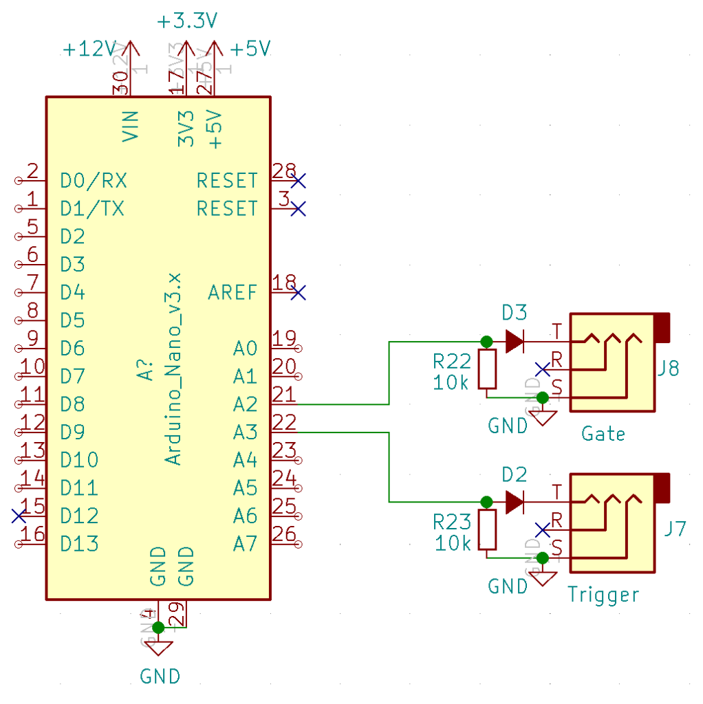
Not much to the gate and trigger outputs really. A diode prevents current from flowing into the Arduino from an external source, and the resistor is very likely unnecessary. I suppose it would ensure that there is a connection to ground even if A2/A3 on the Arduino were to be placed in a floating/input state.
Final Thoughts
Honestly, if you have read all the way through this, bless you. I sincerely hope the article was useful. This was my first project using Kicad and printing PCBs and, as you can imagine, I learned a huge amount along the way. Even now, there are probably a hundred ways to make this module better. And, if you have some of those ideas, I’d love to hear them!
The most important lesson I learned in this process was, to plan on getting it wrong. No matter how hard I tried, there was always some improperly sized footprint, an incorrect trace, or some other bug. Finding it was next to impossible before printing the PCB, and perfectly trivial afterwards. So, if you find yourself meticulously inspecting every wire for the 5th time, just stop, order and assemble the PCB and see why it doesn’t work. It’s soooooo much faster that way.
Happy Synthing!
~finis~

15 thoughts on “Smooth Operator”
Dee
Cool project!
Dr0
This is great, thanks for sharing. I have an old sound card with all of the circuitry all set up. It will be interesting to try using it as it is on the sound card but adding your control stuff.
Tyler in reply to Dr0
I’m not totally sure how to control the ISA bus with an Arduino, but I’m sure there is a way. I think that’s basically what you would have to do in order to interface with the sound card vs. the sound chip itself. Good luck and let me know if it works!
Ed
Excellent page!
I am currently working on something similar, but wit (some) menu-diving.
I use an STM32 Arduino style.
You are welcome to checkout my Playlist on Youtube:
https://www.youtube.com/watch?v=9Y0GE7bLUm0&list=PLWPX-l4AfDQZniisAteWIYz6geY-YyCaP
Tyler in reply to Ed
That’s pretty cool! What sound chip are you using?
Tyler in reply to Ed
Really cool YouTube site btw. There are some pretty sweet projects on there, and the OPL4 device is especially impressive. I would be way too intimidated to take that on!
Ed
I have used the YMF262 in some of the modules, but for this module I used the YMF704 chip (Wavetable mode)
Paula Maddox
Hi, I’m currently doing battle with the YMF262 in 4 op mode, I don’t suppose you’d be able to share your Arduino code?
I’m trying to figure out which operators are connected to which voice/channel, the YMF262 datasheet is difficult to follow.
Tyler in reply to Paula Maddox
The operator layout of the YMF262 should be very similar to the YM3812, but to get to op 3/4 of a voice you need to turn on the second address pin. Check out the article series for the YM3812–especially the first couple of episodes and you should get a good feel for how the registers are laid out. On the YMF262, the OP3/4 addresses should be the same as their op1/2 counterparts.
I’d send you the code for this module, but honestly, it’s a mess and you’d likely be better off adapting the YM3812 code instead.
Also, make sure to turn on the output channels for the operators in both banks. I made that mistake and it drove me crazy when only two of the operators would generate sound. Anyway, good luck and let me know if you get it to work!
Paula Maddox
Thanks, I have it mostly working, are you planning to sell your PCBs?
Would be super nice to have one.
Tyler in reply to Paula Maddox
Glad to hear you got it working! The PCBs definitely still have a few issues / quirks, so I’d probably need to do a new revision before I ever sell them.
X23
Hi, awesome project, any chance to share the PCB?
Tom
hey, love ur design, would u share the design files? would love to give the smooth operator or the soundblaster aynth a shot…thx
Tom
Wow awesome project. Are you selling your pcbs somewhere? Or any downloads …Gerbers or sth?
Tyler in reply to Tom
Hey Tom,
I haven’t been selling the PCBs as they have a few quirks / issues. I think they were the first ones I ever had printed. Perhaps at some point I will redesign them and re-launch. I’m happy to send you the Gerbers if you want them though. 🙂